Anatomy of a Mini Breadboard
Perhaps the single most important yet overlooked and unexciting component in any hobbyists or prototypers arsenal is the humble breadboard.

The modern breadboard is a plug-and-play way to make connections between electronic components. It gets its name from the long-dead practice of using a wooden board ( an actual bread-board if it was handy ) to prototype circuits. Hobbyists would hammer small nails or thumbtacks into the board and wind wires around them to prototype a circuit.
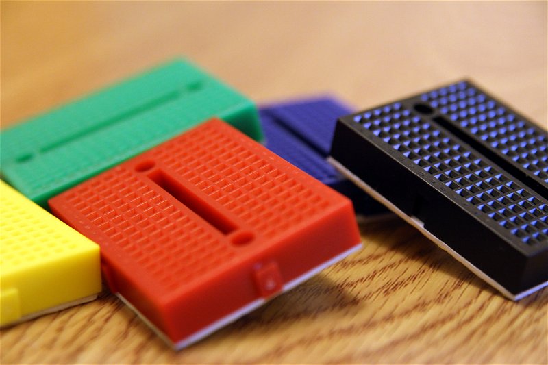
Thanks to Ronald J. Portugal; since 1971 we’ve had convenient plastic boards which tidily pack hundreds of tie points ( also known as contacts ) into a small form-factor suitable for wires, components with long leads, and socketable components with 0.1” Dual or Single in-line pins. These tie points take the form of holes within the breadboard, into which wires and components can be pushed.
They’re useful for basic prototyping, but breadboards don’t accommodate anything with two closely spaced rows of pins, such as the header on the Raspberry Pi. The Pi header needs a special breadboard adaptor to separate the pins so that they sit either side of the central notch. The same applies to many surface mount components, which have two rows of pins ( known as a dual-in-line layout ) and must sit over the central notch.
Throughout this series, we’ll be using the tiny, cheap and convenient 170pt breadboard to host a variety of simple circuits that you can use with your Raspberry Pi.
The 170pt Breadboard
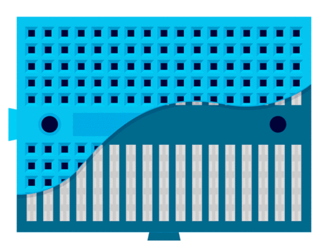
The 170pt breadboard is named for its 170 tie points. It has 17 columns of 10 holes, which are separated into two pairs by a central notch, and labelled 1 to 17. Each column is also labelled, with a letter from A to J to that they can be easily referenced in instructions ( like the squares on a chess board ). These holes contain small metal clips which both secure components to the breadboard and form electrical connections between them.

To understand how to wire circuits on a breadboard, it’s important to remember that each column contains two sets of electrically connected tie-points. One either side of the central groove.
The diagram above shows the metal clips inside a 170pt breadboard, each metal clip is completely isolated from all the others and only connects together the 5 holes in its column.
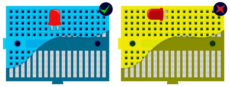
If you plug an LED into a breadboard, for example, it would need to either bridge the central groove, or two different numbered columns. If both legs were plugged into the same column, on the same side of the groove, they’d be connected together. Instead of having current flow through the LED you'd get a short right through the metal clip!

In the above picture, for example, the LED on the left is connected correctly, however the one on the right will never work because both of its legs are connected together!
Unlike its larger cousins, the 170pt mini breadboard doesn’t have power and ground “busses.” These connections usually run the full length of the breadboard and give you a common place from which any column can be powered or connected to ground but you can get by without them.
Most breadboards also have tiny notches which allow them to be connected together. This is great with mini breadboards. The join between two breadboards offers the same functionality as the groove in the middle and is immensely useful for connecting things in series.
The Future Of Breadboards
Some people aren't satisfied with the breadboard as it is. As useful as they might be, there's definitely room for more utility. Avid electronics tinkerers Integreight ( the guys responsible for 1Sheeld ) are looking at ways to make breadboards smarter, allowing them to dynamically configure connections internally based upon a wiring diagram. Cake Board, a better looking, double-sided, LEGO-compatible version of the classic breadboard created by BreadBoardManiac is already available.
Search above to find more great tutorials and guides.