Assembling Picade, 2015 edition
This tutorial will show you how to assemble your 2015 edition Picade. It might also assist if you still have a Kickstarter Picade to put together, you lovely supporter you.
Old tutorial awooga! This tutorial is not for our most recent Picade edition - check out the Picade shop page for a link to the most up to date instructions.
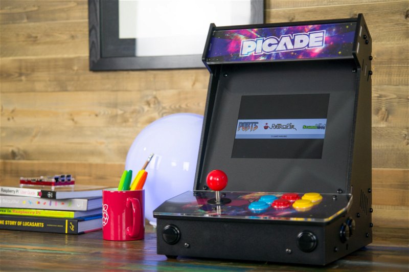
Here's what you'll end up with. Beautiful, huh?

Before we jump into building your Picade, make sure you have everything to hand.
I know you're eager to jump right into the construction, but we need to get set up properly first!
Prepare Your Work Area
A kitchen table is usually a good bet. You'll be very thankful for a nice big workspace when you have the panels all spread out. You'll be using a lot of sharp objects, metal hinges, screws and screwdrivers, so grab a cloth, blanket or some flattened-out cardboard to work on.
Enlist a Friend!
Find a buddy to help build your Picade. Many hands make light work, and there are a lot of small pieces of which to keep track. Be aware of infants with grabby hands!
Allow 2 to 3 Hours
The build should take around 2 to 3 hours. However, by leaving yourself more time you can go at a relaxed pace and be sure not to miss anything.
Nuts and Bolts
There are several different lengths and diameters of bolt in the Picade kit. You should never need to force a bolt through a hole. If you do, then you're probably using the wrong diameter of bolt.
These are M3 and M4 metal bolts and nuts, 3mm or 4mm thick respectively, and also M3 nylon bolts and nuts.
The M3 nylon bolts are for mounting your Pi inside the door. M3 metal bolts and nuts are used for the door catch and Picade board; everything else is M4 metal bolts and nuts.
The Video
You can also watch our complete build video to guide you through the process:
(Note that a couple of bits of the build have changed recently, including the Picade board changing from pink to blue and the retaining clip on the display driver board changing. More on that later.)
Assembly
The best way to assemble your Picade is to attach all the fixtures and fittings to the MDF panels individually and then bolt them together to build the shell. Then, wire up the buttons, add the control panel, and finally add the screen.
Stage 1 - Base Plate & Top
Click here to skip to the right section in our video guide
We're going to start with the base. You will need:
- MDF base panel
- MDF top panel
- 8 fixing blocks
- 8 x M4 bolts, 16mm long
- 8 x M4 nuts
Bolt 6 of the fixing blocks to the base panel. Each block will need only one 16mm M4 bolt, even though there are two holes in each side of the block.
Bolt two more fixing blocks to the top panel. The top doubles as a handle, so populate both holes to provide more strength.
Stage 2 - The Sides & Top
Place the top and base panels out of your build area and get ready to attach fittings to the side panels.
You will need:
- MDF left panel
- MDF right panel
- 2 fixing blocks
- 2 speakers
- 2 hinges
- 1 catch
- 2 x M3 bolts, 14mm long, for catch
- 2 x M3 nuts
- 2 x M4 bolts, 16mm long
- 8 x M4 bolts, 12mm long, for speakers and hinges
- 10 x M4 nuts
Start by attaching a fixing block to each side panel using one 16mm M4 bolt. These should be toward the top edge of the bottom on each panel, as they will secure the control surface to the Picade.
Next, attach a speaker to each side panel. Use two 12mm M4 bolts, diagonally opposite each other, for each speaker.
The left panel will need two hinges along its rear edge. The hinges should fit nicely into the two cutouts. These, like the speakers, will use two 12mm M4 bolts each.
Use the 14mm M3 bolts - the thinner ones - to attach the catch to the right panel.
Stage 3 - Putting It All Together
Click here to skip to the right section in our video guide
Now we're going to put all the individual panels together; your Picade should begin to take shape!
We're going to fit the top to keep your Picade rigid while we bolt other things into it, but you're going to need to unbolt it at one side later, so don't fasten it too tight!
You will need your assembled panels:
- MDF base panel
- MDF front panel
- MDF left panel
- MDF right panel
- MDF top panel
And some fixings:
- 10 x M4 bolts, 16mm long
- 10 x M4 nuts
- 6 black arcade buttons
Start by attaching the front panel to the front side of the base using 16mm M4 bolts.
You will be using the opposite hole on the fixing block to the one that is already populated (as shown in the diagram).
Next, bolt each side onto the base panel, again using M4 16mm bolts.
Finally, slot the top panel between the sides and bolt it securely on one side, but leave it loose on the other so you can undo it easily later.
Push a black arcade button firmly through each hole in the front and sides of your Picade.
Stage 4 - Attaching The Back Door
Click here to skip to the right section in our video guide
- 4 x M4 bolts, 12mm long
- 4 x M4 nuts
- 2 x M3 bolts, 12mm long
- 2 x M3 nuts
- Door catch
First, bolt the catch to the door using M3 bolts.
Bolt the door onto the hinges with the M4 bolts.
Place your Picade to one side and get ready for...
Stage 5 - Building The Control Panel & Installing The Main Buttons
Click here to skip to the right section in our video guide
The control panel houses the joystick and main buttons and is without a doubt the centerpiece of your Picade.
You will need:
- MDF base plate
- Acrylic top plate
- Artwork
- 12 buttons
- Joystick
- 2 x M4 bolts, 16mm long
- 2 x M4 nuts
Unscrew the ball on top of the joystick and remove the plastic dust cover and place them to one side. The ball may be a little tricky the first time you unscrew it. Use a flat head screwdriver in the notch underneath and turn the ball counter-clockwise, if required.
Carefully remove the plastic backing from the acrylic top plate, holding it by the edges and through the button holes to avoid leaving fingerprints or scratches.
Place the MDF base plate with the text labels facing downwards onto your desk. Sandwich the artwork between the MDF control panel base, and the acrylic top making sure it's aligned neatly.
Thread the two M4 bolts through the joystick mounting holes and line them up with the smaller, circular holes on the joystick itself. Bolt them securely down.
Drop the joystick cover back over the joystick, and screw the ball back into place.
Push an arcade button through each remaining large hole. It really doesn't matter which order you put them in.
Stage 6 - Wiring
Click here to skip to the right section in our video guide
Now it's time to add the data-highways (commonly known as wires) into your Picade.
You will need:
- Wiring loom
- Picade board
- Part-assembled Picade
- Small, flat-head screwdriver
- 4 x M3 bolts, 12mm long
- 4 x M3 nuts
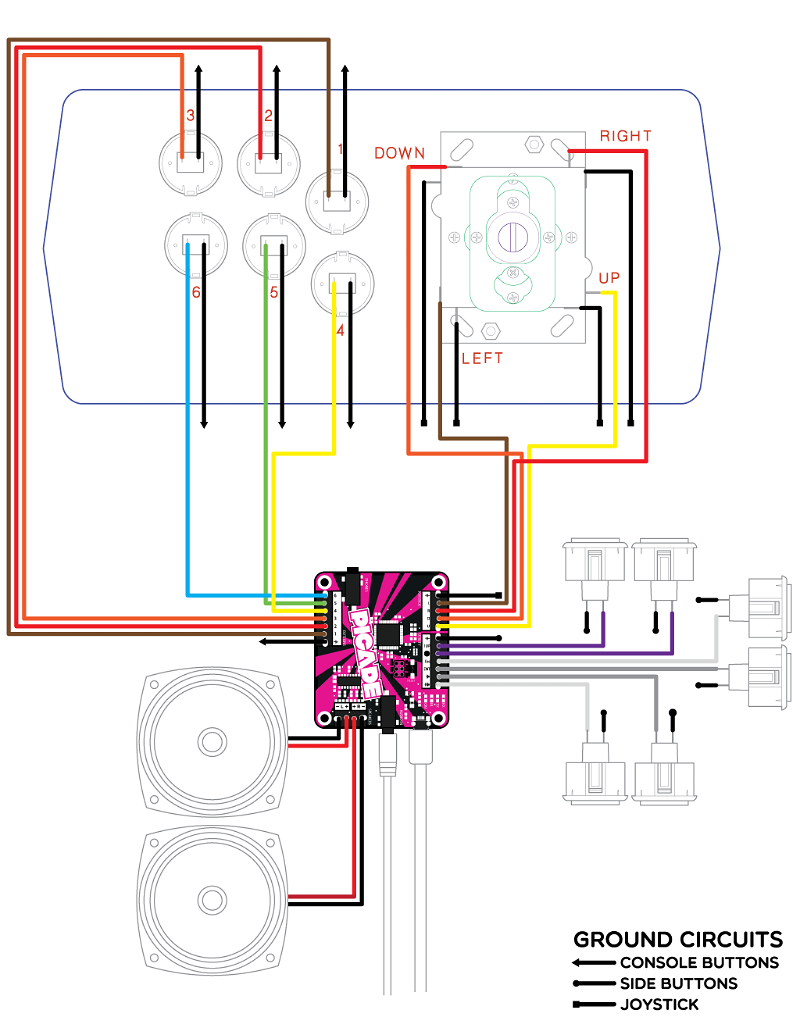
The wiring loom should consist of 5 sets of cables in total:
- Control panel buttons - 7 wires (includes ground)
- Joystick - 5 wires (includes ground)
- Right-hand side buttons - 3 wires
- Left-hand side buttons - 3 wires
- Ground cable for the side and front buttons - this is a long black cable with 6 connectors
You need to make a positive and negative connection between each button and the Picade board. You can do this by looking at the labelling on the inside of the Picade panels, and on the Picade board itself, but we recommend using our handy wiring diagram or watching the build video to save yourself some trouble.

Once you've wired the control panel and Picade board together, you'll need to align the Picade board onto the right-hand edge of your Picade.
You should see some mounting holes for it, and a small circular cut-out for the headphone socket. Lay your Picade on its side and feed four 12mm M3 bolts through the mounting holes.
Slot the Picade board over the mounting holes, and bolt it down with the nuts. Finger tighten them only, making sure it's secure but try not to flex the PCB too much.
Finally, set your Picade to one side and clear some space for the next step.
Stage 7 - Adding The Screen
Click here to skip to the right section in our video guide
You will need:
- Acrylic front panel
- Acrylic screen mount
- Card screen shim
- LCD screen
- LCD driver board
- HDMI cable
- 4 x M4 bolts, 12mm long
- 8 x M4 nuts
Make sure your work surface is free of any bits of grit that might scratch your screen or the front panel, and of any dust which might get trapped in between.
Lay the front panel down with the straight edge facing away from you. That's the top.
Carefully lift up each fixing and thread an M4 bolt through both of the holes, pointing towards you.
Place the card screen shim on top. The black wings on the shim should align with those on the front panel and the bolts should pop easily through the holes.
Screw a nut securely onto each bolt to act as spacers so that the LCD isn't sandwiched too aggressively in the mount.
Lay the LCD screen down on top with the text label facing away from you and the ribbon cable towards you. It's easy to mount it upside-down so we promise not to laugh if you do!
Lay the screen mount on top of the screen and bolt it down with the 4 remaining bolts. Finger-tight only!
Carefully flip the assembly and make sure the LCD screen is perfectly lined up with the shim.
Push a rubber foot through each of the inner-most 3 holes on the LCD mount. It should stick securely to the LCD and prevent it from sliding around.
Prepare the LCD driver board by pushing a plastic adhesive mounting post through each of the 4 mounting holes. Don't peel off the backing yet!
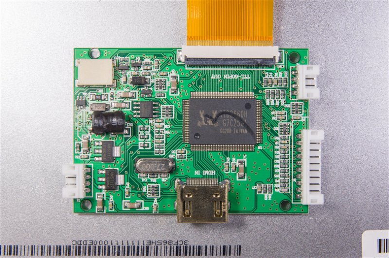
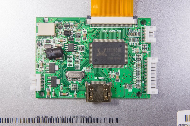
Note that there has been a recent change to the clip on the driver boards.
The newer driver boards have the black clip on the opposite side of the connector to where the ribbon cable inserts, and it flips up and presses back down to retain the cable. Place a finger nail underneath the black clip to flick it open, insert the cable, and then press the clip back down until it clicks in. It should look like the photo below.

The older driver boards have a clip that pulls out from either side. Gently use a fingernail to pull the clips at either side out, making sure not to pull it them too far out and break them. Insert the ribbon cable (it should go over the black clip and under the white part), and then press the black clip back into place, making sure that both sides are pressed all the way in. It should look like the photo below.

Peel the backs off the 4 LCD board mounting posts and place the driver board on the back of the LCD, in line with the ribbon cable. Don't crease it, let it flex naturally. Push down firmly so the adhesive pads stick securely in place.
Stage 8 - Fitting The Screen, Marquee & Artwork
Click here to skip to the right section in our video guide
Now it's time to combine all of your parts into one finished Picade. You will need:
- Mostly-assembled Picade
- Assembled control panel
- 2 x M4 bolts, 16mm long
- 2 x M4 nuts
- MDF top front panel
- Acrylic top front panel
- Marquee art
Undo one side of the top bolts and place them carefully to one side. Making sure the Picade door is open, gently ease the left and right hand sides of the Picade apart and slot the screen into place with the flush edge pointing upwards. Adjust the screen angle as desired using the optional slots provided.
Now sandwich the marquee art between the acrylic and MDF top panels. Don't forget to remove the plastic backing from the acrylic and again beware of finger smudges. Slot the assembly into the remaining slots at the top of your Picade, and push the left and right panels back together.
Bolt the top back into place.
Being very careful not to pull the wires away from the buttons or Picade board, slot the top panel onto your Picade and push it into place.
Drop an M4 bolt into each hole on the top, and with a nut on your finger tip, reach inside the Picade and gently push it against the end of the bolt. Tighten carefully with a screwdriver, making sure not to slip and scratch the console. This part is a little tricky!
Stage 9 - Finishing Touches
The mounting holes for a Raspberry Pi, Beagle Bone Black or Mini ITX motherboard are pretty self-explanatory, so we'll assume you know what you're doing from this point!
Stage 10 - RetroPie
If you're a Raspberry Pi user, we're currently recommending RetroPie as the operating system of choice to run on your Picade.
There are excellent instructions on how to install and configure RetroPie omn the RetroPie website.
After installing RetroPie on an SD card, and before booting it up, make sure you edit your /boot/config.txt and add or uncomment (remove the # before) hdmi_force_hotplug=1. Since the display is powered from the Pi it wont be properly detected at startup, so this is required to make it work.
Search above to find more great tutorials and guides.