Assembling the Display-O-Tron Breakout
The Display-O-Tron breakout uses the same 16x3 LCD display and 3-zone RGB LED backlight as our Display-O-Tron 3000, and is ideal for embedded projects when you need a beautiful little display without the extra bells and whistles that come with the full Display-O-Tron 3000 or HAT.
It also means that you can use your microcontroller of choice to drive it, be it a Raspberry Pi or Arduino of various flavours.
The Display-O-Tron breakout comes unassembled, but worry not, it's just a matter of soldering a few pins and you'll be up and running in no time at all.
Assembly
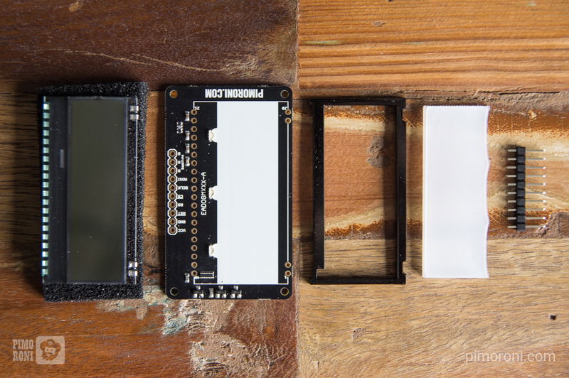
You should have the following items:
- Display-O-Tron breakout
- LCD display
- White acrylic diffuser
- Black acrylic surround
- Strip of male header pins

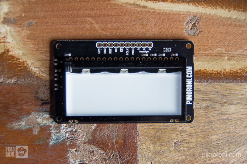
The first thing to do is to peel off the protective film from the two acrylic pieces. They sit between the PCB and the LCD display and diffuse the light from the three RGB LEDs. The white piece sits with the wavy edge nearest the LEDs, and the black piece surrounds it with the cutout for the driver chip at the top left corner. Check the picture below if you're unsure, and make sure that you have the PCB the correct way up, with the large white rectangle facing upwards!
There will also be a piece of protective film on the front of the LCD display, and possibly on the back too, although we try to remove these before packing, so don't panic if it's not there. Peel these off gently using the tabs.

Soldering
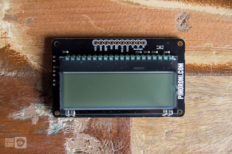
Next, we'll solder the display. It should only really fit one way (provided you have the PCB the correct way up), with the row of 20 pins towards the top of the PCB. Make sure that all of the pins are through all of their respective holes, then flip the whole thing over so that you can solder it.

We have a guide to soldering here so, if you're a soldering noob, check that out for some tips to get you started.
We'd suggest anchoring just one of the corner pins first, checking that it's all aligned correctly, then soldering one of the opposite corner pins to secure the display. Then, solder the remaining pins, making sure that there's a good amount of solder right around the pin and covering the copper contact in a nice dome shape.
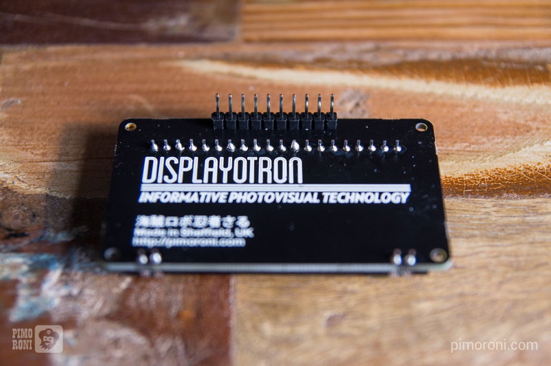
The last thing to do is to solder the strip of header to the PCB. It's your choice as to whether you solder the header to the top or bottom of the breakout. If you're planning on using the breakout on a breadboard then it's best to solder the header to the bottom, otherwise, if you're going to be plugging jumper wires straight into it, then solder a male or female header on top of the board.
Here's how it should look once you're done.

Search above to find more great tutorials and guides.