Driving a 4-digit, 7-segment Display
This tutorials seeks to give you a working knowledge of how 7-segment, multi-digit displays are multiplexed. Multiplexing is the practice of displaying one digit at a time at a very fast rate, and it's why the 4 digits on our 7-segment display can share 8 of their pins. Each digit is only displayed for a fraction of a second before those pins are reconfigured for the next.
We'll also be sneaky, and try to use only the pins on your Pi which were added with the B+, A+ and Pi 2- that's the 14 additional pins on the end. This is useful because you can drive a bubble display in addition to something like a PiGlow or Pibrella.
At the end of this tutorial you should have a display hooked up to your Raspberry Pi that you can drive easily with Python.
Ingredients
I love cramming things on 170pt breadboards, so this entire project will fit tidily on a mini breadboard. You'll need a few wires, and a few resistors.
- 170pt breadboard
- 1x Retro LED 7-Segment Display
- 8x 330Ohm Resistor
- 9 male-to-male Jump wires- the ninth to keep your layout tidy
- 12 male-to-female Jump wires- for connecting to your Raspberry Pi
The Retro Bubble Display

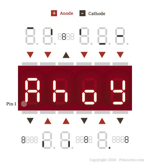
The display itself is simple. It contains a bunch of tiny little LEDs in 4 groups. Each of these 4 groups represents a singal digit and all the LEDs in it share what's called a "common cathode".
To light an LED you need to connect its Anode to VCC and its Cathode to Ground. So to display a number on a single digit we pull its Cathode to ground and power up the Anodes which correspond to the segments we want to show.
You could connect all the cathodes to ground to light all 4 digits at once, but that would mean they all display the same thing. Multiplexing lets you light each digit in turn, faster than the eye can discern, giving the illusion that they're all lit up simultaneously but letting them show different things.
Putting It Together

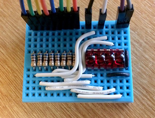
The breadboard layout is simple enough, we directly connect to each of the 4 Cathodes. 3 of them are conviniently located along the bottom of the LED display, but we'll need an extra jump wire to catch that one on the top.
The Anodes, however, need to be connected via a resistor. The easiest way to do this is place all of the resistors in a neat row and use cut-to-length single core wire or jumper-jerky-junior to connect each Anode to one side of its resistor. On the other side we run 8 wires ( 7 segments, plus one dot ) to the Raspberry Pi.
Wiring it up
I used BCM pins 0, 1, 5 and 6 for the Cathodes and pins 12, 13, 19, 16, 26, 20 and 21 for the Anodes. The astute will notice that we're one pin short- I'm going to omit the dot since it's not very useful and I'm trying to squeeze this project into just those extra 14 pins on the 40-way HAT header.
The Code
You'll need RPi.GPIO to drive the LEDs. Import it into Python like so:
import RPi.GPIO as GPIO
GPIO.setmode(GPIO.BCM)
Next you need to set up the Cathodes and Anodes, you can do this by grouping them into lists and iterating through them:
for segment in [12, 13, 19, 16, 26, 20, 21]:
    GPIO.setup(segment, GPIO.out, initial=GPIO.LOW)
for digit in [0,1,5,6]:
    GPIO.setup(digit, GPIO.out, initial=GPIO.HIGH)
You'll also need to "map" the segments. This means determining how the letters a to f and numbers 0 to 9 should look on your display and painstakingly storing these into binary numbers which would look a bit like this:
'''
bit dec segment
0   1   bottom
1   2   Top
2   4   Bottom Left
3   8   Top Left
4   16  Middle
5   32  Top Right
6   64  Bottom Right
7   128 Decimal
'''
letters = {
'a': 0b01111110,
'b': 0b01011101,
'c': 0b00001111,
'd': 0b01101111,
'e': 0b00011111
}
In the above example, each bit ( a 1 or 0 ) of the 8-bit binary numbers stored against each letter in the dictionary letters corresponds to a segment. A 1 means that segment should be turned on for that letter, and an 0 means it should remain off.
Let's take a look at the letter 'b' for example. It's using the number 0b01011101. We count the positions of binary numbers backwards from the LSB ( least significant bit ) which is on the right, to the MSB ( most significant bit ) which is on the left.
We can see that b has bits 0, 2, 3, 4 and 6 set. These correspond to the bottom, bottom left, top left, middle and bottom right segments, or:
|_
|_|
Look familiar? It's a lower case b!
So, given all this setup, how can we display a letter?
segments = [12, 13, 19, 16, 26, 20, 21]

def display_letter(letter):
  '''
  Displays a letter represented as
  a single number from 0-255
  '''
  for bit, segment in enumerate(segments):
    if (1<<bit) & letter:
      GPIO.output(segment,1)
    else:
      GPIO.output(segment,0)

display_letter(letters['d'])
This doesn't actually display the letter- yet- since we have't told the Bubble Display which digit it should look up. We can do that with a digit function:
digits = [0,1,5,6]
def display_digit(digit):
  for other in digits:
    GPIO.output(other,1)
  GPIO.output(digit,0)

display_digit(1)
Search above to find more great tutorials and guides.