Getting Started with Automation 2040 W
Automation 2040 W is a programmable industrial interface board that can interface with high-power devices (up to 40V).
This tutorial covers:
- A tour of the board and its capabilities
- How to power Automation 2040 W
- How to hook it up to external electronics and hardware
- Programming Automation 2040 W with MicroPython using Thonny
- Setting up and running the web page interface example
What you'll need
- An Automation 2040 W (or Automation 2040 W Mini)
- A micro-USB cable (for programming)
- A computer to program from (Windows, Mac or Linux/Raspberry Pi).
If you want to externally power your Automation 2040 W you'll need a few other bits - read on for details!
Automation 2040 W Mini?
If you have the Mini version of this board you can follow this tutorial too - the boards work in exactly the same way. The only difference between the boards is that Mini has fewer digital inputs and outputs and only one relay.
Board Overview
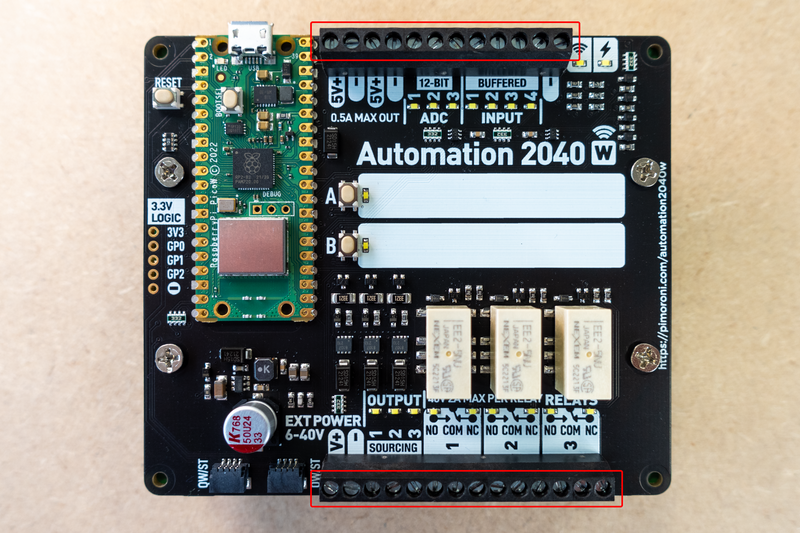
Screw terminals
The connectors on Automation 2040 W are 3.5mm pitch screw terminals that accept a 24-16AWG; 1.0mm² wire and are best tightened with a 2 - 2.5mm flat bladed screwdriver.
These screw terminals are divided into an upper and lower set. The upper set (of 12 positions) is mainly concerned with inputs and contains four digital and three analog inputs. There's also two 5v power outputs (with grounds) that could be useful for powering 5v sensors.
The lower set (of 14 positions) is primarily outputs and contains three current sourcing outputs and three relay switched outputs. This is also where the external power input is located.
Digital inputs
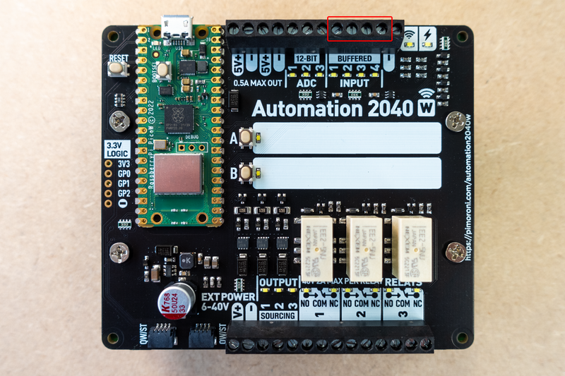 Four fully buffered digital inputs which are activated if the input voltage is between 5 and 40V. Below each input is an indicator that illuminates when the input is activated.
Analog inputs
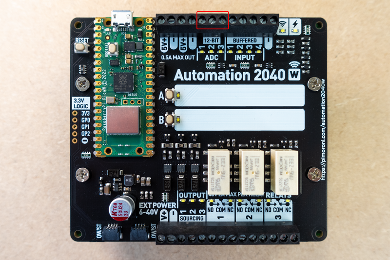 Three analog inputs that can read voltages between 0-40V at a 12-bit resolution. By default, the indicators display different brightnesses depending on the voltage at the related ADC connection.
5V onboard power output
 These terminals can provide 5V at up to 0.5A when the board is powered via an external power input. Very handy when you want to power lower voltage external sensors and other devices that don’t require the high power provided by the output side of the board.
Sourcing outputs
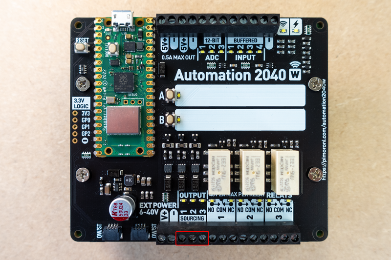
Three high power sourcing outputs. When active these can provide up to 4A at up to 40V current output, great for running big motors, solenoids and other high power devices. The power provided by these outputs is dependent on the power provided to the external power input. Each channel has an indicator LED to show when it is activated.
Relay switched outputs
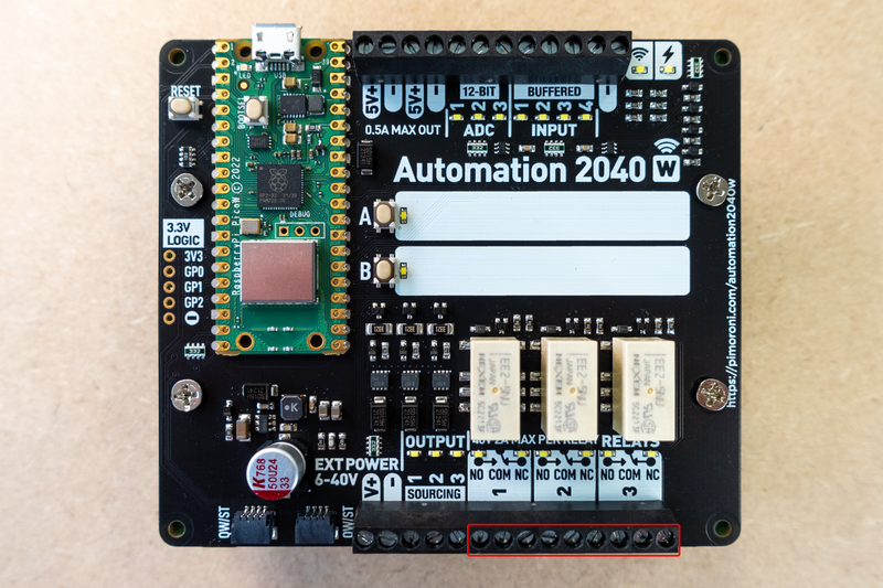
Three relay switches that can operate at up to 2A @ 0-24V and 1A @ 24V-40V. When the relay is inactive, there is a connection between COM (Common) and NC (Normally Closed) , when it is active then there is a connection between COM and NO (Normally Open). The indicator led shows which side of the relay is connected to COM.
Power supply
You can power Automation 2040 W by two methods:
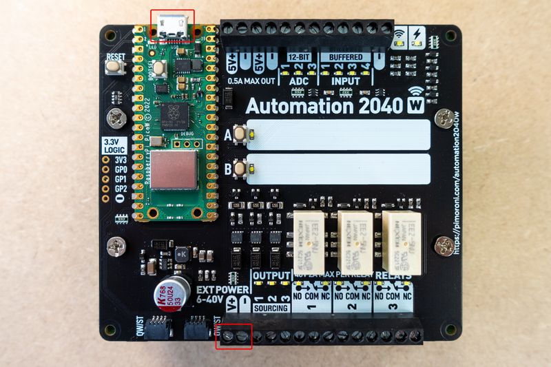
Via the USB micro B connector on the Pico W
You can use this method to power the board whilst programming and debugging the board - the inputs will work plus the LED indicators for outputs and relays. However, the relays will not activate and the outputs (including the 5V output) will not provide any power. This is a nice safe mode to experiment in while getting used to the functionality of the board.
Via the external power input
Connecting power to the external power terminals will fully power the Automation 2040 W and all functions will operate. The relays will activate when commanded to, the outputs will provide power when activated (providing the same power and voltage as the external power input) and there will be 5v available via the 5v output terminals.
It’s fine to have external power and USB connected at the same time.
Qw/ST connectors

The Automation 2040 W has two Qw/ST (Qwiic/STEMMA QT) connectors for expanding the board's capabilities with breakouts (such as LED displays or environmental sensors). If you want to connect up a Breakout Garden breakout that doesn't have a Qw/ST connector, you could use one of these handy adaptors, coupled with a Qw/ST cable.
Hack header
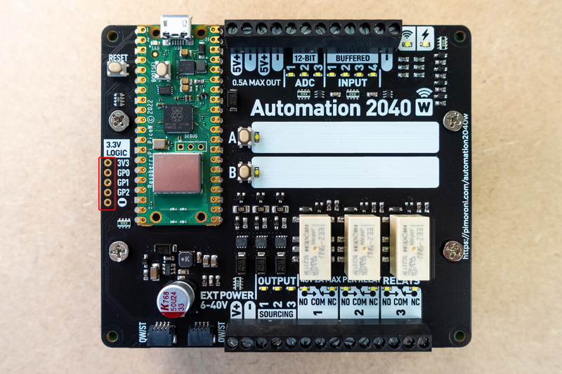
If all of that was not enough, there is also a unpopulated hack header which exposes three of the Pico’s input/output pins - these could be used for communication with UART devices or custom hardware.
⚠️ Warning! These connections are 3.3V only - any higher could permanently damage the Automation 2040 W.
Mounting holes
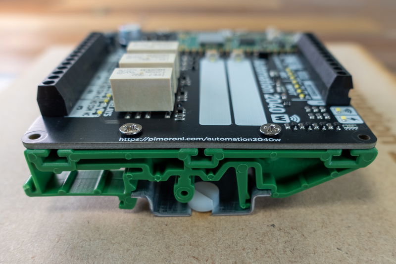
We've included a bunch of mounting holes so you can attach Automation 2040 W to stuff. The four holes in the corners are M2.5. The four holes in the middle are M3 - we've used them to mount our board on a section of DIN rail using these DIN rail mounting clips.
Powering Your Automation 2040 W from External Power
To get full functionality from your Automation 2040 W you'll want to provide it with a tasty external power supply. If you'd like to hook up external power, you'll need:
Two colours of wire - we’re using red and black to avoid confusion.
An external power supply between 6-40V with enough current to power all the external devices you want to use. We’re using our 9V 18W supply which is more than enough for this demo.
A socket barrel jack to screw terminal adaptor. This lets you avoid having to cut the barrel jack off the power supply to get at the bare wires!
Cut two equal lengths of wire, we’ll be using red for +V and black for GND. Strip each end of the wire exposing about 5mm. If you're using multi stranded wire make sure you twist the conductor strands together, ensuring all the strands are twisted together to avoid short circuits.
Take the barrel jack adaptor and insert the wires into the screw terminals (+ to red, and - to black) and use the screw to secure them tightly. At this point, we’d recommend using a multimeter to check the polarity is as expected. Plug in the power supply and set your multimeter to voltage mode - we’re using a 9v power supply, so our red/+ wire should measure +9V. Remember to disconnect the power supply before continuing.
On the Automation 2040 W insert the wires in the EXT POWER screw terminals and use the screws to secure them tightly.
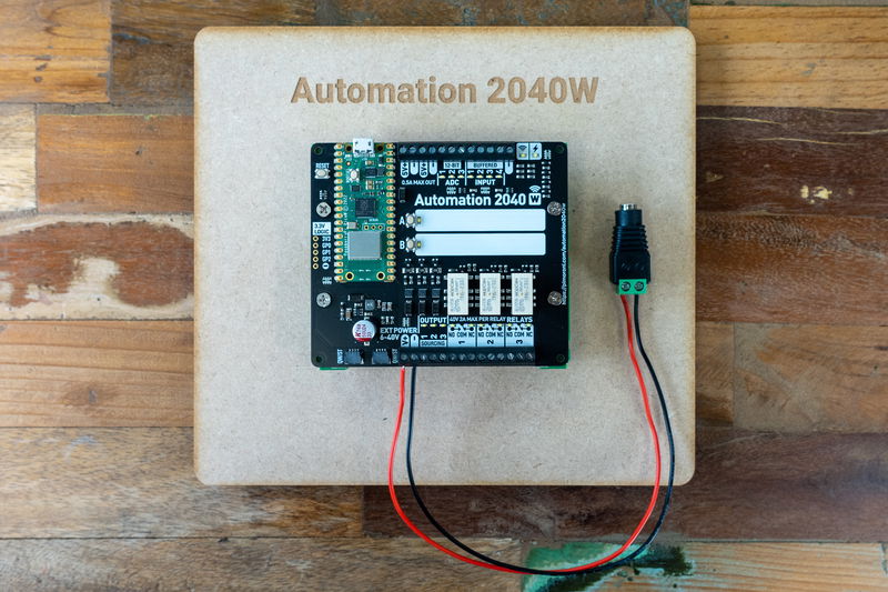
It is best to do some quick checks using the continuity mode of a multimeter just to make sure everything is connected correctly before powering up. The centre pin of the adaptor should be connected to the V+ external power screw terminal and the ring of the adapter should be connected to the GND external power screw terminal. There should be no continuity between the V+ and GND screw terminals. If you find any issues here you should recheck your wiring to make sure everything is correct and retest.
You are now ready to fully power your Automation 2040 W. Plug in the power supply, if everything is correctly connected the power indicator on the top right corner of the board should be lit.
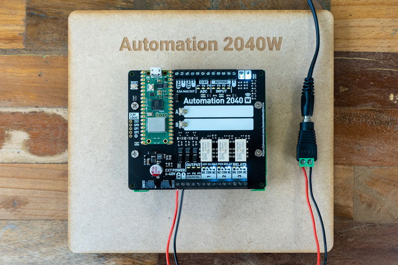
(We're already running some code on this Automation 2040 W, which is why the wireless LED is lit up as well).
MicroPython and Automation 2040 W
To get all the functionality out of the Automation 2040 W (including wireless capabilities) we recommend using the latest version of our custom MicroPython build. It contains lots of helpful functions to help get you up and running with your shiny new Automation 2040 W.
Installing MicroPython
Automation 2040 W doesn’t come with any pre-installed firmware as the use case is really up to the end user, so first of all you'll need to download our most recent 'Batteries Included' MicroPython image, and copy it to the Pico W.
If you're brand new to Raspberry Pi Pico/RP2040s, you might find the step by step instructions in our Getting Started with Raspberry Pi Pico tutorial useful - it will show you how to install our custom MicroPython build and goes into more detail about how to use Thonny . Here's a quick TLDR!
Download the most recent MicroPython .uf2 from the Releases page of our pimoroni-pico Github repository. Click on 'assets' to expand the list of files - you'll want the 'picow' image for Automation 2040 W.
Connect Automation 2040 W to your computer with a USB cable.
- Hold down the BOOT button of Automation 2040 W, and then tap the RESET button. This will put it into bootloader mode, and it should appear as a drive on your computer called RPI-RP2.
- Copy the .uf2 file to the RPI-RP2 drive - once you've done that Automation 2040 W will reboot.
Programming Automation 2040 W with Thonny
Once MicroPython is installed, Automation 2040 W won't show up as a drive on your computer any more. To program it, you'll need to talk to it through an interpreter - we're using Thonny, which is available for Windows, Mac or Linux.
- Install Thonny
- Open up Thonny. Make sure the interpreter (shown in the box on the bottom right corner) is set to 'MicroPython (Raspberry Pi Pico)'.
- Plug Inky Frame into your computer, if it's not plugged in already.
- The flashing cursor next to the >>> in the 'Shell' box tells you that Automation 2040 W is talking to your computer and is ready to accept instructions. If you don't see the MicroPython prompt in the shell box, try pressing the red stop button in Thonny to interrupt whatever it's doing.
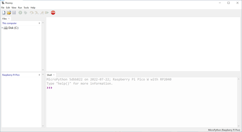
⚠Couldn't find the device automatically?
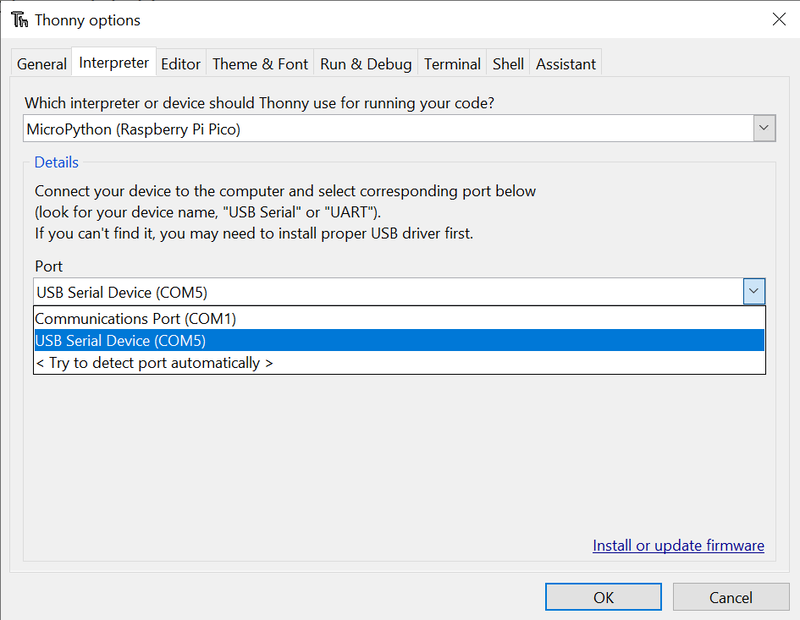
Our version of Thonny didn't manage to detect our board automatically - probably because the Pico W image is based on brand new v1.19 MicroPython. We had to specify the port our device was using, you can do this by clicking on 'MicroPython (Raspberry Pi Pico) at the bottom right, and selecting 'Configure Interpreter'. Select your device under 'Port' - ours was showing up as 'COM5.
Usage examples
Here are some simple code snippets to demonstrate the functions of Automation 2040 W, using on board and external hardware.
⚠ Note that if you have an Automation 2040 W Mini you can init your board with board = Automation2040WMini to see the correct number of digital inputs/outputs and relays.
Blinking the onboard LED
This is a pretty straightforward example of how to blink the comms LED. Copy and paste this code into a new tab in Thonny, and then click on the 'run' button.
from automation import *
import time

board = Automation2040W()

while (1):
    board.conn_led(True)
    time.sleep(0.5)
    board.conn_led(False)
    time.sleep(0.5)
Using a value between 0 and 100 instead of True or False will adjust the brightness of the LED.
Reading the onboard buttons
This example reads the A and B buttons and toggles the associated LEDs on and off.
from automation import *
import time

board = Automation2040W()

toggleA=False
toggleB=False

while (1):
    if (board.switch_pressed(SWITCH_A)):
        toggleA = not toggleA
        board.switch_led(0, toggleA)

    if (board.switch_pressed(SWITCH_B)):
        toggleB = not toggleB
        board.switch_led(1, toggleB)

    time.sleep(0.5)
Reading inputs
⚡ Note that the following examples all require external power to be connected for the outputs/relays to become active! ⚡
The inputs on Automation 2040 W are tolerant up to 40V and will trigger above 4.5V. To demonstrate this you can connect the 5V output to one of the inputs with a jumper wire.
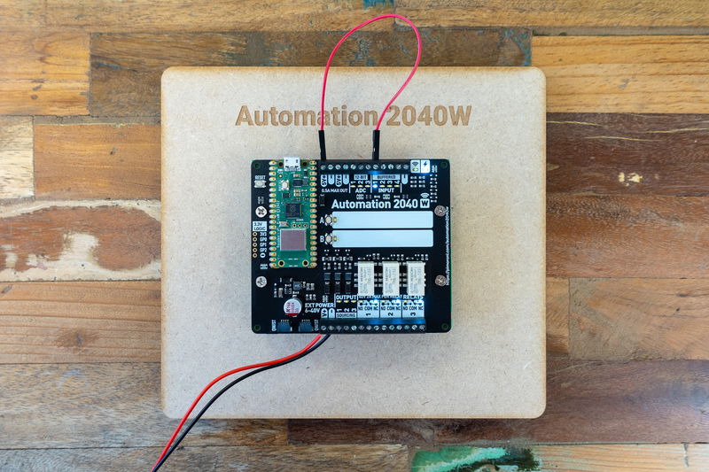
You can read the results like this:
from automation import *
import time

board = Automation2040W()

while (1):

    print (board.read_input(0),board.read_input(1),board.read_input(2),board.read_input(3))
    time.sleep(0.5)
Reading analog inputs
The analog inputs (ADCs) can read and measure an input range from 0-40V. In this example we will be using the 5V output to read a potentiometer.
Connect the 'out' pins of the potentiometer to 5V output and -/ ground. Connect the wiper (that's the centre pin on this particular pot) to one of the ADC channels.
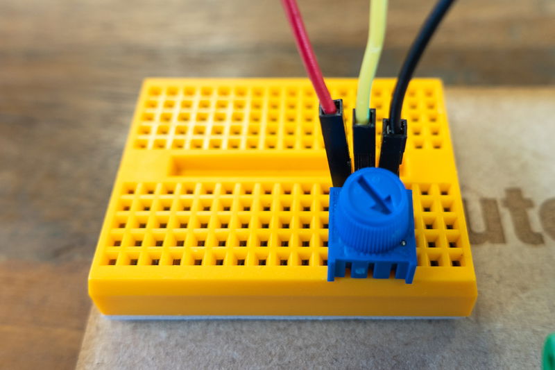

from automation import *
import time

board = Automation2040W()

while (1):

    print (board.read_adc(0),board.read_adc(1),board.read_adc(2))
    time.sleep(0.5)
Toggle output
The outputs on Automation 2040W are sourcing outputs, which means that they provide current to whatever device that you wish to connect. To use them you will need to connect the positive lead of your device to the output you wish to use and the negative lead to and GND or - terminal as shown below.
This code toggles a device connected to output 1 on and off when button A is pressed.
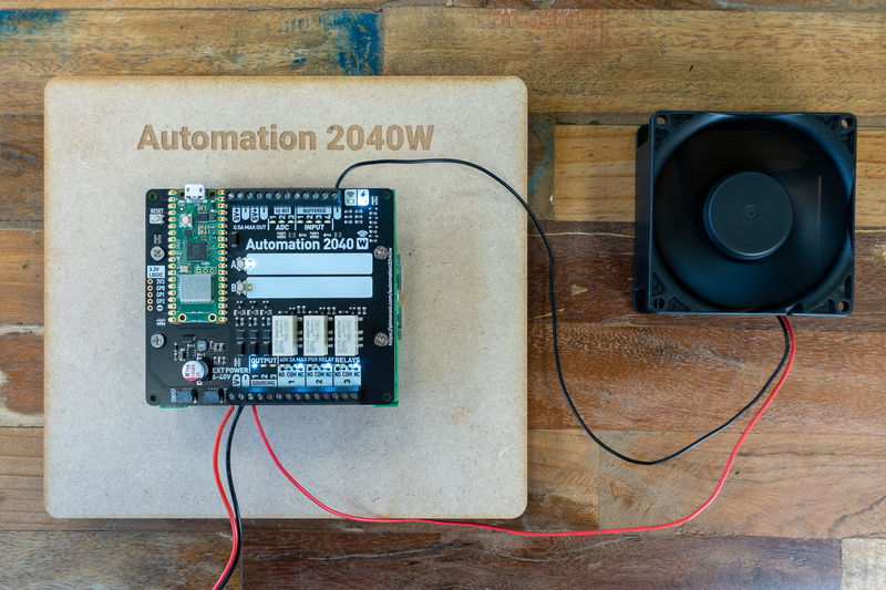
Note: The outputs provide the same voltage level as the external supply voltage you provide at the EXT POWER input terminal.
from automation import *
import time

board = Automation2040W()

toggle=False
outputToToggle = 0

while (1):
    if (board.switch_pressed(SWITCH_A)):
        toggle = not toggle

    board.output(outputToToggle, toggle)
    board.switch_led(0, toggle)

    time.sleep(0.5)
Toggle relay
Relays are mechanical switches that can be turned on and off by a microcontroller. They can either be used on the high side (between power and your external device ) or the low side (between your device and ground). The relay by default is connected between COM (Common) and NC (normally closed) and when the relay is activated the connection switches to between COM and NO (normally open). Relays can be used to switch devices with different voltages to the EXT POWER input, which is handy!
For this demo, we've connected the positive wire of our big chunky motor to EXT POWER V+, so that it's sharing the power from the our power supply. We've then connected the negative/ground wire of the motor to the NO terminal of relay 1, and connected the COM terminal to one of Automation's grounds to complete the switch.
from automation import *
import time

board = Automation2040W()

toggle=False
outputToToggle = 0

while (1):
    if (board.switch_pressed(SWITCH_A)):
        toggle = not toggle

    board.relay(outputToToggle, toggle)
    board.switch_led(0, toggle)

    time.sleep(0.5)
More Examples
You can find all the Automation 2040 W examples at the link below:
Copy and paste the code into a new tab in Thonny (if you click the 'raw' button on Github first it will make it easier to copy and paste). Press the green run button in Thonny to run the code.
Web interface example
This guide assumes that you have already installed the latest version of pimoroni-pico MicroPython onto your Automation 2040 W. If this is not the case please scroll back up to the MicroPython and Automation 2040 W section.
Our examples include a web page interface, which uses the wireless capabilities of the Pico W to let you interact with Automation 2040 W's functions via a tiny web page (all hosted on the Pico W!) To run code that uses wireless, you'll need some to clone or download some supporting files and libraries from Github.
Adding supporting libraries
On the front page of the pimoroni-pico repo, click on the green code button and select 'download ZIP' - this will download the whole repo to your computer. Unzip it somewhere where you can find it easily.

Then, switch back to Thonny. For the next step you'll need to have the Files window visible in Thonny, you can open it up with 'View > Files'.
The top box can be used to browse the local files in on your computer, and the bottom box shows the files on Automation 2040 W. Find your unzipped repo and navigate to micropython/examples/common in the top box.
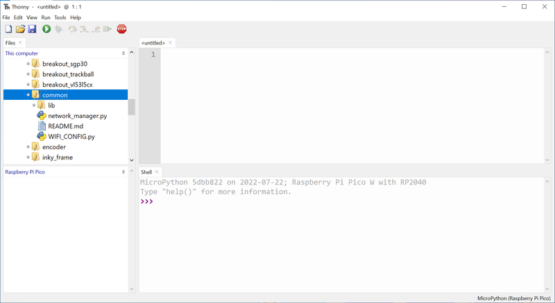
You'll need a bunch of stuff out of the micropython/examples/common/lib folder to run the examples, so you might as well grab the whole thing - right click on lib in the top box and select 'Upload to /' to transfer it to your Pico (if you'd rather just install the libraries we're going to use for this example, you just need tinyweb and logging.mpy). You'll also need network_manager.py and WIFI_CONFIG.py, so right click on those and upload them to your Pico as well. Once you're done, the files on your Pico W should look something like this:
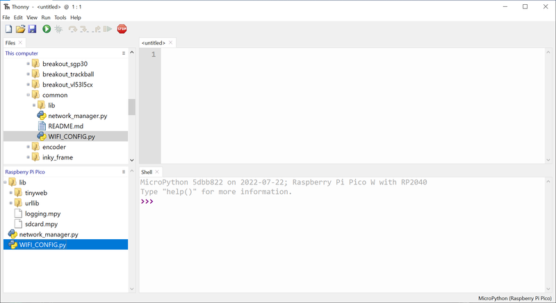
Note that network_manager.py and WIFI_CONFIG.py should be in the root directory of your Pico W, and the other libraries should be inside a folder called lib.
Adding Wi-Fi credentials
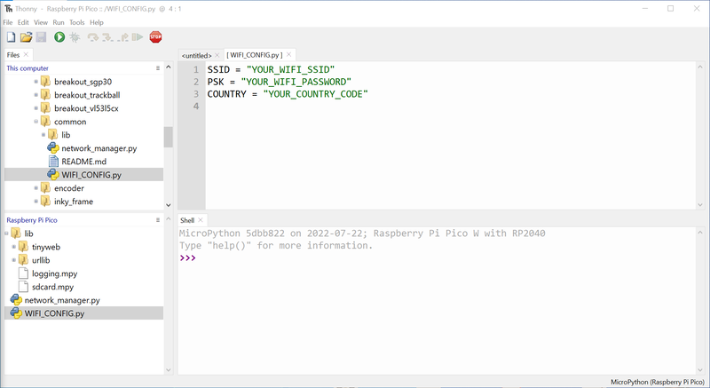
For us to be able to connect to the web interface, your Pico W will need to know your wireless network details. Double click on the copy of WIFI_CONFIG.py that's on your Pico W to open it up in Thonny. Add your network's SSID, password and country code (if you're in the UK like us then your country code should be "GB" - if not check this list). Note that SSID and password are case sensitive! Once that's done, click save.
Running the web interface example
To copy the example itself to the Pico W navigate to micropython/examples/automation2040w/web_io_interface in the downloaded repo. Upload index.html and main.py to your Pico. We're saving the example as main.py so it will run automatically when the Pico W is powered up.
If you run the example when it's connected to your computer, it will show you the IP address of the device once it's connected - take note of it (you may need to run the example twice to install and initialise the extra MicroPython modules needed to run the webserver).
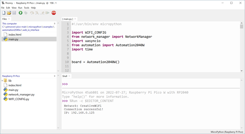
Open a web browser and type in the the IP address you have noted down.

Tada - you should now be able to view all of Automation 2040 W's inputs and control the outputs from your browser.
Search above to find more great tutorials and guides.