Getting Started with Interstate 75
Interstate 75 is our range of RP2040 and RP2350-powered driver boards for HUB75-style panels - the LED matrix panels that you sometimes see making up big fancy billboards or scrolling LED signage. We've made it so it can slot tidily into the back of a panel, with minimal extra hardware required. You can also get an Interstate 75 W which has wireless internet connectivity.
This tutorial will show you how to plug things in and how to start making things light up, and it includes basic getting started instructions for both MicroPython and CircuitPython.
⚠ 02/2025 - This guide been updated to work with our new standalone Interstate 75 repo and all three flavours of Interstate 75 - Interstate 75, Interstate 75 W (Pico W Aboard) and Interstate 75 W (RP2350)
What you'll need
- An Interstate 75 or Interstate 75 W
- A USB cable for programming (USB-C for Interstate 75 and Interstate 75 W (RP2350), USB micro-B for Interstate 75 W (Pico W Aboard))
- One (or more) RGB LED matrix panels
If your project involves many panels, lots of brightness or you just want to run it untethered from your computer, you'll may want to power it with an external 5v power supply attached to Interstate 75's screw terminals. An easy way to breakout wires from a barrel jack power supply is with a screw terminal block (the kind with a socket).
Power
You can power Interstate 75 and a couple of LED panels via the USB connector (if you're drawing a modest amount of power) or through the screw terminals. LED matrix panels are hungry beasties - officially a 64x64 panel can consume up to 4 amps of electricity. Unofficially, you will probably get away with a lot less ampage than this if you're using it for things like displaying text or numbers and not driving the panels hard - we've had our examples running happily on four 64x64 panels from a 2A supply.
If your panels are in need of a power supply upgrade you might see dimness, glitching, flickering or find your Interstate 75 is constantly rebooting.
For this tutorial, we're going to assume that you're powering everything through the USB-connector on Interstate 75.
Connecting up one panel
This section shows how to hook up a single panel to Interstate 75. If you have a Interstate 75 W Starter Kit then scroll on down to the next section and we'll show you how to plug in that specific hardware.
HUB75 panels have 16 pin data in and data out connectors on the back - you'll need to plug Interstate 75 into the data in connector. The backs of the panels should all have arrow markings which you can use to see the direction in which the data should be flowing through the panel.
Here are the backs of some of the panels we stock with the data in connector marked in red. Markings and layouts may vary slightly from batch to batch!
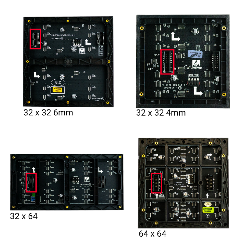
Go ahead and plug the pre-soldered socket header on Interstate 75 into the data in connector on your panel. The data connector has a nubbin on one side of it so you can only plug it in one way.
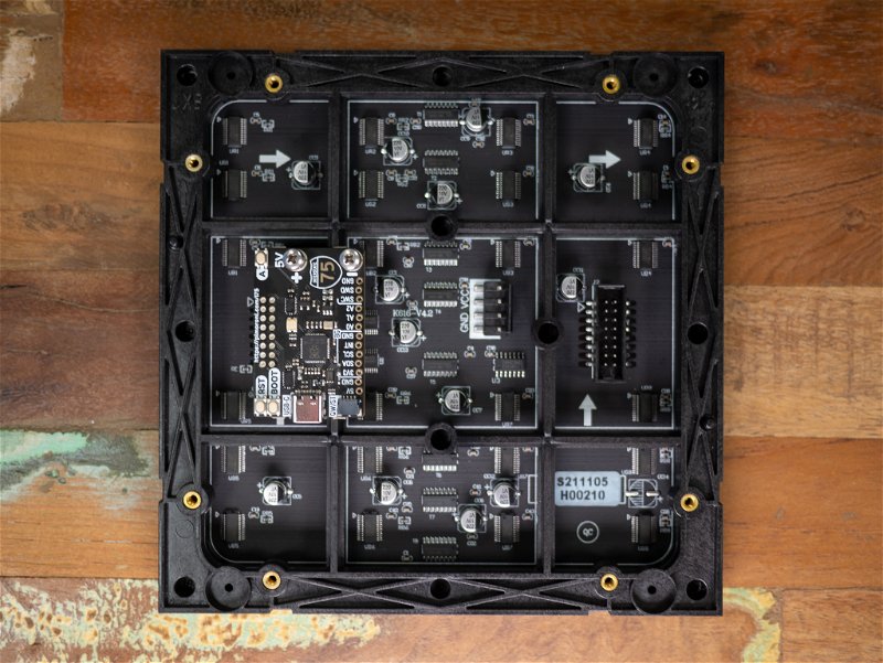
Connecting the power cable
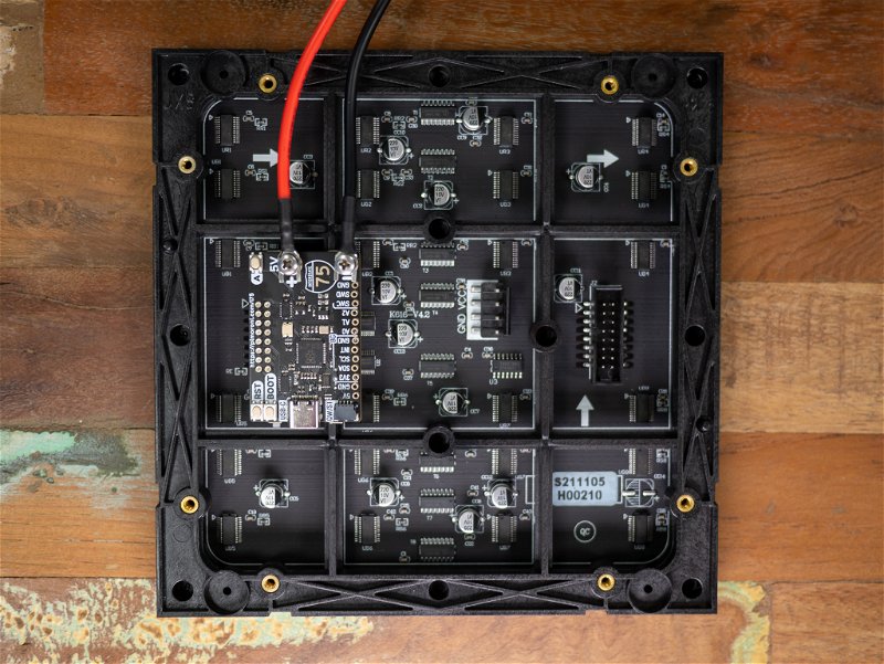
The 16-pin connector on Interstate 75 will only provide a data signal to the panel, it won't provide it with enough electricity to power it. To power the panel, you'll need to connect it up to the screw connectors on Interstate 75, using the red and black power cable that comes with the panel. Loosen up the screws and slot the fork in-between the screw and the metal post, then tighten up the screws and give the wires a little tug to check they're securely held in place. Make sure you have the polarity correct - red to + and black to -.
The other end of the cable has a white plug on it - plug this to the power connector on your panel (marked 'power' on some panels, or just VCC and GND on others). The clippy part of this connector means it should also only go in one way round, though there's no harm in double checking that the red wires go into VCC and the black wire is connected to GND.
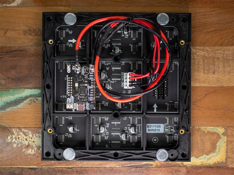
We've also attached the little magnetic feet that you get with the panel - they're useful if you want to stick your project to a metal surface like a noticeboard or your fridge.
Connecting up multiple panels
Our shiny new Interstate 75 W Starter Kit comes with two 128 x 64 LED panels that can be chained to make a big square 128 x 128 pixel or rectangular 256 x 64 pixel display. Here's what you get in the kit:
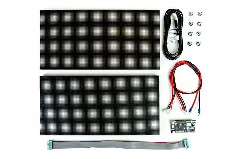
- Interstate 75 W (RP2350)
- 2x 128x64 RGB LED matrix panels
- A red and black double ended power cable with ring connectors
- A grey data cable for chaining multiple panels
- 8x magnetic feet with screw threads
- A nice long USB-C cable
Lay your panels LED-side down with the text on both panels and the arrows pointing in the same direction. We've got our panels arranged in a square, but if you'd rather arrange your in a line with the short edges together that's fine - they'll be wired up in exactly the same way.
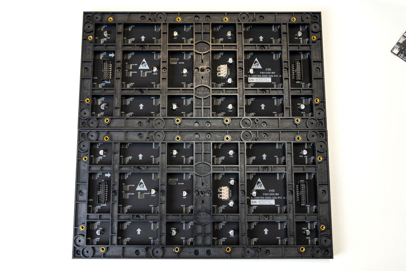
Plug the pre-soldered socket header on Interstate 75 W into the data in connector on the first panel in your chain. The data connector has a nubbin on one side of it so you can only plug it in one way.
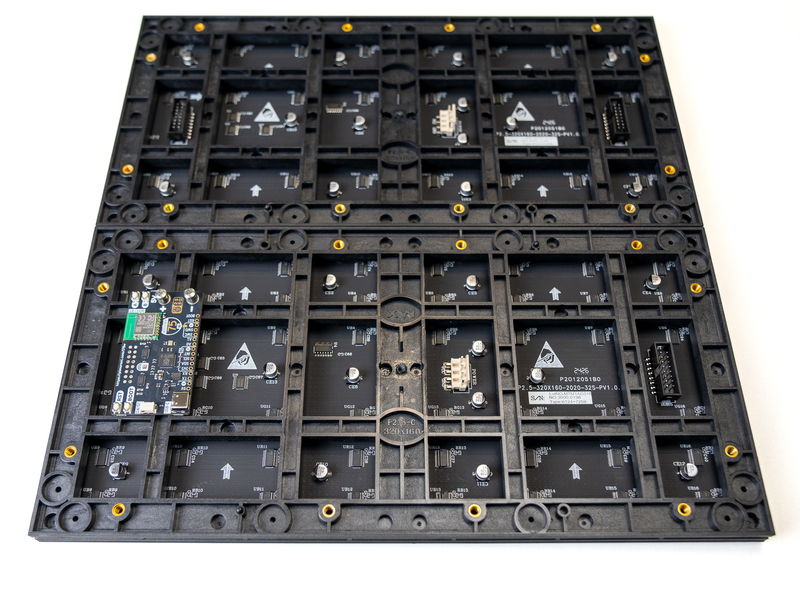
Next we're using the grey data cable to connect the panels. One end goes in to the data out connector on the first panel (this is the panel that has Interstate 75 W plugged into it), and the other goes to the data in connector on the second panel.
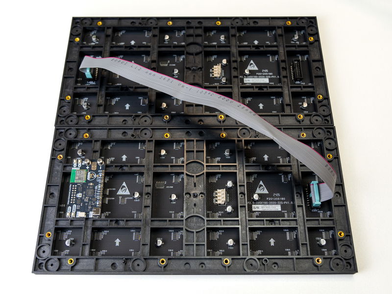
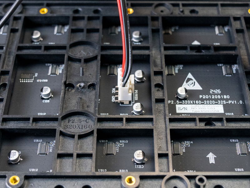
Each panel will need providing with power as well as data, so we need to use the double ended red and black power cable to connect both panels to Interstate 75 W. First we're connecting the power cable up to the panels, using the pair of 4 pin connectors. Clip these onto the corresponding 4 pin power connectors on the panels. They should only go on one way, with the red wires going to VCC, and the black wires going to GND.
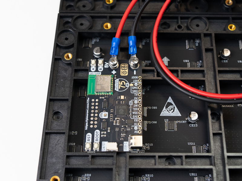
To connect the power cable to the Interstate board, first use a small cross head screwdriver to remove the two screws from the screw terminals. Then thread the screws through the red and black ring connectors and screw them back into place. Make sure the polarity is correct, with the red wire going to the terminal marked + and the black wire going to the terminal marked -.
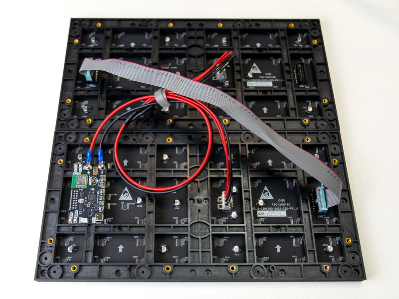
Here's what the panels look like with both cables in place. We've added a cable tie to tidy up the slack on the power cable.
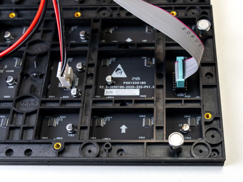
Next we're adding the magnetic metal feet:
Finally, plug the USB-C cable into the board.
⚠ LED panels can draw a lot of current! If you're using more than one panel and want to make totally sure that your computer is protected from accidental over-current mishaps we'd recommend hooking up an external power supply whilst you program Interstate 75 (or disconnecting power from the panels). However, modern computers and power supplies should have circuitry to protect themselves from this sort of thing and we've not had any problems powering Interstate and a few panels from our computer.
What configurations of panels are supported?
PicoGraphics only currently supports certain layouts of chained panels - you can find a list of sizes of matrices that are supported at the link below.
MicroPython and Interstate 75
The LED matrix drivers in our C++/MicroPython build make use of RP2040 (and RP2350)'s programmable IOs and DMA to update the LEDs quickly in the background, minimising CPU usage and maximising colour depth. Our library will let you set individual pixels to a RGB colour value.
You can also use our tiny graphics library PicoGraphics on your Interstate 75 board, which gives you a convenient way of getting text, shapes, vectors and images onto your LED matrix.
Installing our custom MicroPython build
Interstate 75 comes without firmware, so you'll need to install MicroPython as your first order of business. If you're brand new to Raspberry Pi Pico/RP2040/RP2350, you might find the step by step instructions in our Getting Started with Raspberry Pi Pico tutorial useful - it will show you how to install our custom MicroPython build and goes into more detail about how to use Thonny . Here's a quick TLDR!
- Download the most recent MicroPython .uf2 from the Releases page of our interstate75 Github repository. You'll want the
i75w_rp2350.uf2 for Interstate 75 W (RP2350),i75_rp2040.uf2 for Interstate 75 or thei75w_rp2040.uf2 for Interstate 75 W (Pico W Aboard). The-with-filesystembuilds come with examples built in, but note that flashing one of these will overwrite your existing filesystem, so be sure to back up any important code to your computer before flashing one of these. - Hold down the BOOT or BOOTSEL button and then press, and release, the RESET button. This will put it into bootloader mode, and it should appear as a drive on your computer called RPI-RP2 or RP2350, depending on what kind of board you have.
- Copy the .uf2 file to this drive - once you've done that Interstate 75 will reboot running Pirate brand MicroPython (it won't show up as a drive anymore).
- Install Thonny
- Open up Thonny. Make sure the interpreter (shown in the box on the bottom right corner) is set to 'MicroPython (Raspberry Pi Pico)'. If everything's working as it should look something like this. The flashing cursor next to the >>> in the 'Shell' box tells you that Interstate is talking to your computer and is ready to accept instructions!
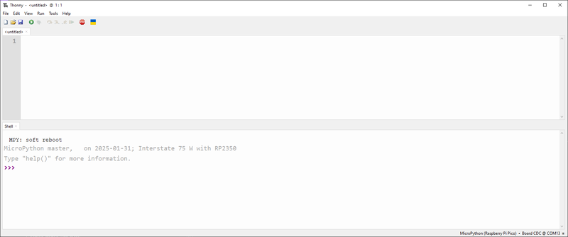
If you're having trouble using Thonny to communicate with your board, there's some troubleshooting suggestions at the link below:
Running the examples
Interstate 75 W (RP2350)
Examples built for the new and shiny RP2350-based Interstate 75 W can be found here. Note that they're written for use with the big LED panels that come in the Starter Kit, so may need modifying to work nicely with smaller displays.
If you flashed the with-filesystem .uf2, they'll come pre-loaded on your device. If not, you can copy and paste the code from Github into a new tab in Thonny. To see the files on your device (and to be able to copy files from your computer) you'll need to have Thonny's 'Files' window open - if you don't see it it you can enable it with View > Files. The files on the device are displayed in the bottom window - double click on an example to open it up, and press the green play button in the toolbar to run it.
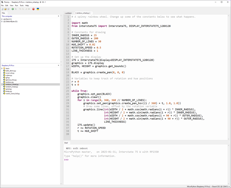
Interstate 75 and Interstate 75 W (Pico W Aboard)
Examples for our older RP2040 based boards can be found here - the generic examples are good to start with as they don't need any dependencies. If you click on the raw button it makes it easy to copy and paste them into the top box in Thonny. Press the green run button in the toolbar to run the code!
The examples in the 75W directory use Interstate 75 W's wireless functions and may require extra files to be installed. You can find WIFI_CONFIG.py and network_manager.py in our pimoroni-pico repo, in examples/micropython/common.
Using PicoGraphics
As of early 2022 you can now use PicoGraphics (our inhouse tiny graphics library) with Interstate 75, woo! Here's how to get started.
Before you do anything else you'll need to import the interstate75 library - this library includes a bunch of helpful shortcuts for working with the functions on the Interstate board. You'll then need to set up an instance of the Interstate75 class. Start your code off like this - you can either copy and paste this code into a new tab in Thonny and press the run button when it's complete, or enter it line by line in the REPL (that's the bottom box with the >>> prompt in it).
from interstate75 import Interstate75

i75 = Interstate75(display=Interstate75.DISPLAY_INTERSTATE75_128X128)
graphics = i75.display
i75 is our board - so we'll be using that when we want to do something physical with the board functions, like reading a button or updating the matrix. We need to specify what size matrix we have - we're using a 128 x 128 matrix but there's a list of other sizes you can use on the page below.
graphics is our graphics buffer - we'll be using that when we want to use one of our fancy PicoGraphics functions like drawing a shape, changing pen colour or drawing some text.
Lighting up the onboard RGB LED
Here's a code snippet that lights up Interstate 75's onboard RGB LED red :
from interstate75 import Interstate75

i75 = Interstate75(display=Interstate75.DISPLAY_INTERSTATE75_128X128)
i75.set_led(255, 0, 0)
The three numbers after set_led are an RGB (Red Green Blue) colour code, and each number should be between 0-255.
Using the buttons
Here's a simple example of how to do stuff with the buttons, using the functions and constants in interstate75. This example makes the RGB LED different colours when you press the A, B or BOOT buttons.
from interstate75 import Interstate75, SWITCH_A, SWITCH_B, SWITCH_BOOT

i75 = Interstate75(display=Interstate75.DISPLAY_INTERSTATE75_128X128)

while True:
    if i75.switch_pressed(SWITCH_A):
        i75.set_led(255, 0, 0)
    elif i75.switch_pressed(SWITCH_B):
        i75.set_led(0, 255, 0)
    elif i75.switch_pressed(SWITCH_BOOT):
        i75.set_led(0, 0, 255)
Lighting up the matrix
PicoGraphics keeps track of colours by using pens. If we want to draw something, we'll first need to set up a pen colour. As with the LED, the colour is specified by an RGB colour value. Each colour can be represented by mixing a particular amount of Red, Green, and Blue, from 0 to 255, meaning that you can get over 16 million different colours!! As an example, pure red is 255, 0, 0 and white is 255, 255, 255.
from interstate75 import Interstate75

i75 = Interstate75(display=Interstate75.DISPLAY_INTERSTATE75_128X128)
graphics = i75.display

MAGENTA = graphics.create_pen(255, 0, 255)
Once we've created a pen we'll need to tell PicoGraphics to use it:
graphics.set_pen(MAGENTA)
Clearing the display after you've used set_pen will fill it with the current pen colour:
graphics.clear()
Once you've finished drawing with graphics commands, we can update the LED matrix like this:
i75.update()
Adding some text
You can draw multiple things to the graphics buffer before triggering a update - here's a little hello world program that uses a few different coloured pens:
from interstate75 import Interstate75

i75 = Interstate75(display=Interstate75.DISPLAY_INTERSTATE75_128X128)
graphics = i75.display

MAGENTA = graphics.create_pen(255, 0, 255)
BLACK = graphics.create_pen(0, 0, 0)
WHITE = graphics.create_pen(255, 255, 255)

graphics.set_pen(BLACK)
graphics.clear()

graphics.set_pen(MAGENTA)
graphics.text("hello", 1, 0, scale=1)
graphics.set_pen(WHITE)
graphics.text("world", 1, 6, scale=1)
i75.update()
When using the text function you'll need to specify the position the text is going to be on the screen. Pixels are organised by their x/y coordinates from the top left hand corner, so the top left pixel is 0, 0. Remember that, in Python, things are numbered from 0 rather than from 1.
Perhaps you'd like your message to flash? To do that we'll need to incorporate some time.sleep() commands to add some short pauses in our code, and put all the drawing code into a while True: loop, so it runs multiple times :
from interstate75 import Interstate75
import time

i75 = Interstate75(display=Interstate75.DISPLAY_INTERSTATE75_128X128)
graphics = i75.display

MAGENTA = graphics.create_pen(255, 0, 255)
BLACK = graphics.create_pen(0, 0, 0)
WHITE = graphics.create_pen(255, 255, 255)

while True:
    graphics.set_pen(MAGENTA)
    graphics.text("hello", 1, 0, scale=1)
    graphics.set_pen(WHITE)
    graphics.text("world", 1, 6, scale=1)
    i75.update()
    time.sleep(0.5)

    graphics.set_pen(BLACK)
    graphics.clear()
    i75.update()
    time.sleep(0.5)
Congrats - you're well on the way to opening your own kebab shop!
You can find out more about the things you can do with PicoGraphics (including drawing shapes, illuminating individual pixels and displaying images) at the link below:
Lighting raw pixels on the matrix
If setting individual pixels is all you need for your application you could use the raw hub75 module and its set_pixel function instead of PicoGraphics.
import hub75

WIDTH = 128
HEIGHT = 128

matrix = hub75.Hub75(WIDTH, HEIGHT)

matrix.start()

matrix.set_pixel(0, 0, 255, 0, 0)
The first two digits are which pixel you want to update (0, 0 is the one in the top left corner) and the last three digits are the RGB colour code.
To clear any pixels that you've set, you can use the clear() function:
matrix.clear()
Find out more about the hub75 module at the link below.
MicroPython troubleshooting
We've found some matrix panels have hardware differences which may mean you need to tweak some settings. If you're getting a weird, glitchy top row on your matrix or if the right LEDs aren't lighting up, try initialising your matrix like this:
i75 = Interstate75(display=Interstate75.DISPLAY_INTERSTATE75_128X128, stb_invert=True)
If your matrix isn't lighting up at all when you run the examples (and if you aren't getting any errors in Thonny), first double check that Interstate 75 is plugged into the 'data in' connector on your matrix. If it is, it might be worth giving this option a go - some newer panels have a FM6216A driver chip that requires different register settings to work.
i75 = Interstate75(display=Interstate75.DISPLAY_INTERSTATE75_128X128, panel_type=Interstate75.PANEL_FM6126A)
The LEDs on some HUB75 panels have a different colour order - fun! If your blue is coming out green and your green is coming out blue you can switch the order our library uses like this:
i75 = Interstate75(display=Interstate75.DISPLAY_INTERSTATE75_128X128, color_order=Interstate75.COLOR_ORDER_RBG)
Other colour orders are available, check the hub75 function reference for more info:
CircuitPython (RP2040 boards only)
CircuitPython drivers are designed to work on a bunch of different microcontrollers so you won't get the fancy RP2040-architecture specific tweaks that you'll find in our library. You will get access to Adafruit's mighty DisplayIO library though, which gives you lots of tools for displaying all sorts of different kinds of text, shapes and images.
Installing CircuitPython and libraries
To install CircuitPython -
Download the Interstate 75 CircuitPython .uf2 (if you have a Interstate 75) or the Pico W .uf2 (if you have an Interstate 75 W (Pico W Aboard)). You'll probably also need the CircuitPython driver bundle (be sure to grab the one that matches the version of CircuitPython that you just downloaded)
Hold down the BOOT button of Interstate 75 (or BOOTSEL on Interstate 75 W), and then press, and release, the RESET button. This will put it into bootloader mode, and it should appear as a drive on your computer called RPI-RP2.
Copy the CircuitPython .uf2 to the RPI-RP2 drive. After a few seconds, it should reappear as a drive called CIRCUITPY.
With CircuitPython, you always save your code as
code.py, and it will run automatically. You don't need to use Thonny, you can editcode.pywith any text editor. Using Thonny or Mu as your editor is handy though, as it lets you view the serial console which can be useful for debugging error messages.
Running the examples
You can find some RGB matrix code examples in RGB LED Matrices with CircuitPython. To use them with Interstate 75 or Interstate 75 W, just point them at the right pins when initialising your matrix object. You'll need to do this differently for Interstate 75 and Interstate 75 W, as the pins have different names.
32 x 32 or 32 x 64 matrix (Interstate 75)
matrix = rgbmatrix.RGBMatrix(
    width=64, height=32, bit_depth=3,
    rgb_pins=[board.R0, board.G0, board.B0, board.R1, board.G1, board.B1],
    addr_pins=[board.ROW_A, board.ROW_B, board.ROW_C, board.ROW_D],
    clock_pin=board.CLK, latch_pin=board.LAT, output_enable_pin=board.OE)
64 x 64 (or bigger) matrix (Interstate 75)
matrix = rgbmatrix.RGBMatrix(
    width=64, height=64, bit_depth=3,
    rgb_pins=[board.R0, board.G0, board.B0, board.R1, board.G1, board.B1],
    addr_pins=[board.ROW_A, board.ROW_B, board.ROW_C, board.ROW_D, board.ROW_E],
    clock_pin=board.CLK, latch_pin=board.LAT, output_enable_pin=board.OE)
32 x 32 or 32 x 64 matrix (Interstate 75 W)
matrix = rgbmatrix.RGBMatrix(
    width=64, height=32, bit_depth=3,
    rgb_pins=[board.GP0, board.GP1, board.GP2, board.GP3, board.GP4, board.GP5],
    addr_pins=[board.GP6, board.GP7, board.GP8, board.GP9],
    clock_pin=board.GP11, latch_pin=board.GP12, output_enable_pin=board.GP13)
64 x 64 (or bigger) matrix (Interstate 75 W)
matrix = rgbmatrix.RGBMatrix(
    width=64, height=64, bit_depth=3,
    rgb_pins=[board.GP0, board.GP1, board.GP2, board.GP3, board.GP4, board.GP5],
    addr_pins=[board.GP6, board.GP7, board.GP8, board.GP9, board.GP10],
    clock_pin=board.GP11, latch_pin=board.GP12, output_enable_pin=board.GP13)
Using the buttons and LED
Here's a quick example of how to use Interstate 75's buttons and RGB LED in CircuitPython. You'll need to grab adafruit_rgbled.py and simpleio.mpy from the library bundle and pop them in your lib folder on CIRCUITPY.
For Interstate 75:
import board
import digitalio
import adafruit_rgbled
import busio

button_boot = digitalio.DigitalInOut(board.USER_SW)
button_boot.direction = digitalio.Direction.INPUT
button_boot.pull = digitalio.Pull.UP

button_a = digitalio.DigitalInOut(board.SW_A)
button_a.direction = digitalio.Direction.INPUT
button_a.pull = digitalio.Pull.UP

led = adafruit_rgbled.RGBLED(board.LED_R, board.LED_G, board.LED_B, invert_pwm = True)

def button_read(button):
    return not button.value

while True:
    if button_read(button_a):
        led.color = (0, 255, 0)
    if button_read(button_boot):
        led.color = (0, 0, 255)
For Interstate 75 W:
import board
import digitalio
import adafruit_rgbled
import busio

button_a = digitalio.DigitalInOut(board.GP14)
button_a.direction = digitalio.Direction.INPUT
button_a.pull = digitalio.Pull.UP

button_b = digitalio.DigitalInOut(board.GP15)
button_b.direction = digitalio.Direction.INPUT
button_b.pull = digitalio.Pull.UP

led = adafruit_rgbled.RGBLED(board.GP16, board.GP17, board.GP18, invert_pwm = True)

def button_read(button):
    return not button.value

while True:
    if button_read(button_a):
        led.color = (0, 255, 0)
    if button_read(button_b):
        led.color = (0, 0, 255)
If you're interested in learning how to do things with wi-fi in CircuitPython, check out the link below!
Next steps
Now that you know how to drive an LED matrix with a RP2040, how about hooking up a Breakout Garden breakout and using it to display sensor data, like temperature and humidity? You could attach an encoder and make an RGB Etch-A-Sketch. Or a real-time clock so that your giant holiday countdown timer keeps track of time when it's powered off?
Search above to find more great tutorials and guides.