170pt Projects Part 2: Let There Be Light
If you haven’t read our intro to the 170pt mini breadboard, now is the time to do so. In this first example we’ll start simple, with the canonical Raspberry Pi circuit example: lighting an LED.
While it’s easy to light an LED, there’s a lot of thought that goes into doing it properly. Every LED you use should be paired with a suitable resistor to prevent it drawing too much current and simply burning itself out.
LEDs will be rated for a certain amount of current, your Pi supplies another amount of current ( and in many cases will happily try to supply far more than it really should ) and thus your resistor choice should be appropriate for these values.
What is current?
This question is a little beyond the scope of this article, but in simple terms Current is the “rate of flow” of electrical charge. Voltage, on the other hand, is the “potential difference” between two points. This is in many ways analogous to the flow of water, with Current being the volume of water and Voltage being the pressure difference between two points. Think of a “resistor” therefore as a narrowing in the pipe that limits the amount of current flow.
How much current can the Pi supply?
Your Raspberry Pi takes a 5v power supply, and the processor is powered at 3.3v. To achieve this 3.3v a voltage regulator is used to power the CPU. When designing the Pi, the foundation used a figure of 3mA per pin when determining how much current this regulator should have spare for GPIO.
This means you have a soft limit of 3mA on each of the 17 Pi GPIO pins, but in reality this all comes from a pool of 51mA which can be divided as you see fit- as long as no single pin supplies more than 16mA.
The 3.3v power pins on the Pi are also connected to this regulator, and subject to the same overall limit but can exceed the 16mA of a GPIO pin.
Finally, the Pi has a 5v power pin, but we’ll leave that for another article.
In summary:
- Your Pi can supply up to 51mA on its GPIO pins
- Any single pin can supply up to 16mA
- Your Pi also has some 3.3v power pins, which draw from this same pool of 51mA but can supply more than 16mA
How much current does an LED require?
This question can only be answered by the datasheet associated with your choice of LED. You’ might get a leaflet if you buy a grab-bag, otherwise you’ll need to look up the “Forward Current” and “Forward Voltage” of your chosen LED either on the website where you bought it, or delve into the manufacturers website.
My first grab-bag contained LEDs rated between 8mA and 12mA depending on their colour, but you might find yours will take up to 20mA- more than you’ll want to be drawing from your Pi.
How do I calculate which resistor I should use?
Now it gets a little tricky, but only a little. The maths to calculate the correct resistor value is fairly straight-forward, but the value you get out of your calculation won’t exactly match an available resistor. You have two options in this case:
- Use the nearest higher available resistor, this is fine in almost all instances
Or
- Create your own resistor value using networks of other resistors, you’ll only ever want to do this out of curiosity!
For our purposes, we’ll do A, but B is a topic we’ll cover in another article.
You need a few values for your calculation, they are:
- Supply Voltage - if you’re using a Pi, this will be 3.3v
- LED Forward Current - probably around 5 mA to 20 mA
- LED Forward Voltage - red/green could be around 2v, blue/white around 3v
The calculation is:

( Supply Voltage ( Volts ) - LED Forward Voltage ( Volts ) ) / ( LED Forward Current mA / 1000 )
For for a lovely blue LED, at 3v and 20mA:

( 3.3v - 3v ) / ( 20mA / 1000 )
1.3v / 0.02mA = 15Ohm - nearest available resistor is 15Ohm, or Red - Green - Black
As expected, the resistance value is pretty low because the gap between a Blue LEDs 3v and the Pi’s 3.3v is small.
For a little green LED at 2v and 20mA:

( 3.3 - 2 ) / ( 20 / 1000 )
1.3 / 0.02 = 65Ohm - nearest available resistor is 68Ohm, or Blue - Grey - Black
Now that you know the maths and how to pick an appropriate resistor, you’ll be able to make an educated guess for what value you should use.
Generally at 3.3v you can use around 68Ohm and at 5v around 125Ohm, but we tend to use values a little higher than this to remain on the safe side. One of the reasons for this is resistor tolerance. You may be using "gold" band resistors, which have a tolerance of 5%. That means their value can be 5% greater, or 5% less than specified. A 100Ohm resistor could be 95Ohm or 105Ohm. Picking a higher value, so you never accidentally get a lower one, is good practise!
Most Pi guides will recommend 330Ohm, and we do too! These will make sure you’re operating safely with more or less any LED you’ll ever throw at your Pi.
The astute reader will have noticed that we calculated these values at 20mA, and that this is more than the 16mA each pin on the Pi is rated for. The LEDs don't actually need anywhere near this 20mA and in reality will probably be perfectly bright at just 5mA.
In fact it’s technically wrong to connect LEDs directly to the GPIO pins on your Pi but if you use a 330Ohm resistor you won’t do any harm.
There are more correct ways to do it. These involve interesting things like Transistors, Darlington Arrays and Shift Registers, all of which allow your Pi’s 5V power pin, capable of providing much more current, to be the source of power. We’ll cover these in a later article!
Which way ‘round does my LED go?
You may or may not know it, but LED stands for Light Emitting Diode. Yes, LEDs are diodes and thus they inherit the properties of a diode, specifically that they will generally only allow current to pass through them in one direction.
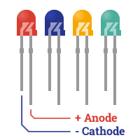
LEDs have an Anode and a Cathode, the positive and negative terminals respectively. Most LEDs have only two legs, but some may have 3 or more in which case they will have a single leg which is known as the Common Anode or the Common Cathode.
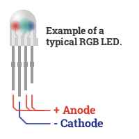
An example is single package RGB LEDs, which actually contain 3 LEDs and will have 4 legs. 3 of which take the power for the Red, Blue and Green LEDs and the 4th is the Common Cathode- or their common connection to ground.
The negative side, or Cathode, of the LED will generally have a flat edge on the LED itself and a short leg. The positive side, or Anode, will have a longer leg and a rounded side.
The flat edge rule isn’t true of all LEDs, specially those that aren’t rounded, so it’s a good idea to always make sure you trim the short lead slightly shorter than the long lead when cutting the legs of your LED down to size.
The leg-length rule isn’t concrete, either. RGB LEDs, for example, can have a longer cathode and anodes of varying lengths.
There’s one golden rule, however. If your LED is clear, and you can peer inside, you might notice that the shorter leg, or Cathode, is generally connected to the larger part inside the LED. The same is true of RGB LEDs, the Cathode will always be connected to the larger part inside.


So, remember:
- The Anode is Positive,
- usually the longer leg,
- always and the smaller bit inside the LED
- The Cathode is Negative,
- usually the shorter leg,
- always the larger bit inside the LED,
- and sometimes a flat side
LEDs aren’t all that delicate, so you can always use a safe choice of resistor ( 330Ohm or greater for most Pi projects ) and simply connect your LED in different ways until it lights up.
Let the show begin
So you should now know how to identify the Anode, Positive, and Cathode, Negative, legs of your LED. You should also know how to calculate the appropriate value resistor to get the best result. And you should also know that connecting LEDs directly to the GPIO pins of your Pi isn’t really the right thing to do.
But we like instant gratification, so we’re going to do it anyway!
You’re going to need:
- Your LED
- The right value resistor, or 330-to-560Ohm to play it very safe
- A 170pt mini breadboard
- A male to female jump wire for Ground ( black recommended! )
- A male to female jump wire for Power ( red recommended! )
From what you learned about the 170pt breadboard in [link]part 1 of this series[/link], coupled with your new found knowledge of LEDs, you should be able to figure out how to place the components yourself.
But if not, never fear!
- Place your LED so that it bridges two of the rows on your 170pt breadboard
- Bend the legs on your resistor and bridge the row that the Anode, Positive ( long leg ) of your LED is plugged in to, to yet another row
- Connect your red jump wire to your resistor ( the side that’s not connected to the LED! )
- Connect your black jump wire to row that the Cathode, Negative ( short leg ) of your LEG is plugged in to
You should now have a simple circuit set up. To avoid having to get into the gnitty-gritty of making one of your Pi’s GPIO pins go HIGH and provide 3.3v, we’re going to cheat and connect the red wire directly to a 3.3v power pin on your Pi.
To be on the safe side, we’ll use the 5th pin up on the bottom left of your Pi’s GPIO connector ( Pin 17, 3v3 Power )- this is nice and far away from the 5v pin which we don’t want to accidentally connect to!
Then connect the black wire to the bottom left pin ( Pin 25, Ground ).
Your LED should light up! If it doesn’t, check it’s the right way around by looking for the various clues. Also, check that the connections between the wires, resistor and LEDs are correct- remember the LED and resistor should share a row so that they are electrically connected!
The next steps!
Now that you’ve made the most fundamental circuit, and hopefully learned a thing or two about resistors and LEDs, you’re ready to move on to the next article in this series where we’ll be adding more LEDs and turning them on and off from your Pi. See you there!
Search above to find more great tutorials and guides.