Programming the Adafruit Trinket from your Raspberry Pi
Warning: Make sure you use the 3.3v Trinket, don't connect a 5v one directly to your Pi!
Why Combine A Trinket And A Pi?
The Trinket and the Pi are a very complementary pair. The Trinket can do many things that your Pi either can't do, or isn't great at:
- Generate PWM ( Pulse-width-modulation ) signals, for Servos/Variable LED brightness
- Read cheap analog sensors, such as temperature or light intensity
- Generate precisely timed signals, like the one needed for WS2812 LEDs
- Very quickly reacting to events
The trinket is a cheap and flexible alternative to a PWM driver, or an analog to digital converter. One that you can not only use with your Pi, but as a stand-alone controller.
The skills you pick up from tinkering with a Trinket and learning how to program it will also be transferable should you decide to try any Arduino products. The Trinket has 8 pins. There are 5 digital IO pins. Two of these can be configured as analog inputs and two as PWM outputs. The last can be either PWM or analogue. The 3 remaining pins are reserved for power, ground and reset.
What you'll need
To get your Trinket and Pi connected, you’re going to need a few bits and bobs.
- A 3.3v Adafruit Trinket
- 6 female to male jump wires for power/programming
- 2 extra wires for Serial
- Two 4-pin male headers
- A 170pt breadboard
- An LED
- A suitable resistor
- A Raspberry Pi ( model A or B will do ) running Raspbian
If you have male to male wires and an extra breadboard handy you can use the Adafruit Pi T-Cobbler to clarify where the SPI, power and Serial pins are.
Configuring The Software
You’ve got two choices when it comes to setting up the software. If you’re running Raspbian you can just grab the contents of our GitHub repository. We’ve put together a simple setup script which will get you set up in a jiffy, just:
git clone https://github.com/pimoroni/programming-trinket-with-raspberry-pi
cd programming-trinket-with-raspberry-pi
./setup-raspbian
This should install the Arduino IDE, the modified avrdude ( used for flashing programs to your Trinket ) and Arduino-Makefile which makes it easier to compile your Arduino programs from the command-line and avoid the Arduino IDE itself.
Alternatively you can manually install each component from the GitHub repo, and I'll assume you know what you're doing!.
Connecting Them Together
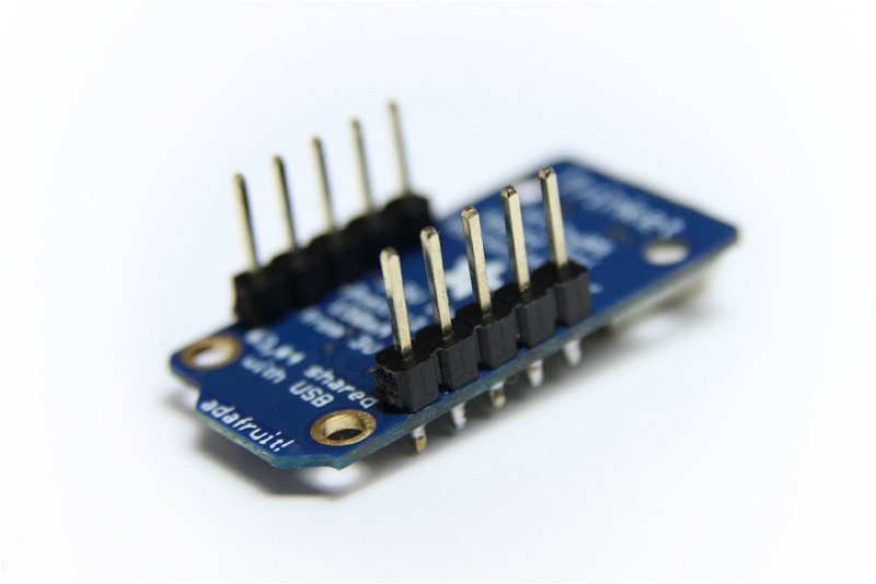
First, solder two 4-pin male headers to your Trinket pointing downwards. This will let you push it into a breadboard and keep it securely positioned for tinkering.

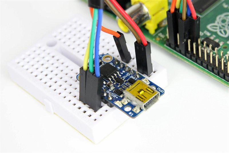
You should then pop the Trinket into the 170pt breadboard. Align it so that the USB port hangs over one edge, although we won’t be programming the Trinket over USB it’s a handy source of power.

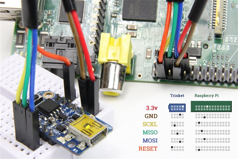
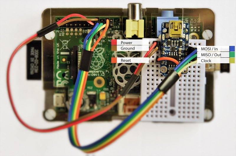
Once you’ve got the Trinket set up on your breadboard you need to make the power and SPI connections to it from your Raspberry Pi GPIO header. If you’re doing this on a breadboard you’ll need 6 female-to-male jump leads; power, ground, mosi, miso, clock, reset.

First connect GPIO 8 on your Raspberry Pi to the Reset pin on the Trinket. GPIO 8 is the second to bottom most pin on the right of the Pi GPIO header.
Next you will need to connect up the pins that do the programming. These three pins are known as MOSI, MISO and SCK - these catchy names stand for “Master Out, Slave In”, “Master In, Slave Out” and “Clock.”
When connecting the Trinket, which is our slave device, we want to connect these to SPI In, SPI Out and SPI Clock. If you’re following, that’s MOSI on the Pi to the second pin down on the right of the Trinket and then work your way through MISO and SCK on the Pi, and down on the Trinket- the pins are in the same order.
Finally, connect the power and ground connections. These are next to each other on the top left of the Trinket ( the USB port is on the top ). I suggest using the 3.3v Power and Ground pins towards the bottom of the Pi header, since these are both comfortably close to the SPI pins you’ll be using, and a safe distance from the 5v pin.

Time To Test
To test that you’ve connected the Trinket up correctly, you can ask avrdude to look for it. To do this run:
avrdude -c gpio -p attiny85
And you should see something like:
avrdude: AVR device initialized and ready to accept instructions

Reading | ################################################## | 100% 0.00s

avrdude: Device signature = 0x1e930b

avrdude: safemode: Fuses OK

avrdude done.  Thank you.
Next, you can compile and upload the Blink sketch that we’ve provided in the GitHub repo:
cd examples/blink
make upload
Playing With The Examples
To get you started, we’ve included some example code in the GitHub repository that should compile and upload straight onto your Trinket. These include an i2c NeoPixel driver, basic reading-writing of the EEPROM ( the Trinkets non-volatile memory ), Serial and a standard Blink.
What's That .h File?
You might notice that all of these examples include a header file, that’s the file ending with ”.h”
void setup();
void loop();
void blink(unsigned int delayms);
This header file is included into the top of the Sketch file and includes the function prototypes. Prototypes are the basic skeleton of your functions with no executable code. The Arduino IDE normally creates these for you automatically, but since we’re not using the IDE it’s a little extra step you have to remember.
Without function prototypes you can’t call a function until it’s been defined, which can lead to some less-desirable structuring of you code- forcing all your functions to the top, rather than the bottom where they're tidily out of your way. It’s better to create a header file so you can arrange functions in your Sketch logically.
Final notes
Once you’re comfortable connecting the Trinket and the Pi you should switch to using the 5v pin on your Pi to power the Trinket, specially if you’re using the 3v output to drive something like NeoPixels.
Search above to find more great tutorials and guides.