Getting started with ESP IoT pHAT

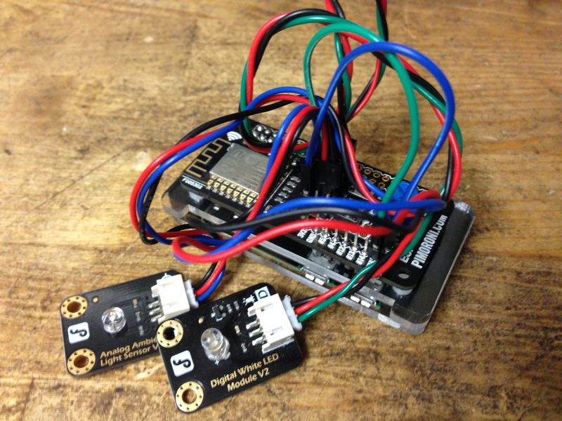
The ESP8266 is arguably one of the hottest microcontrollers right now, and at the heart of many Internet of Things (IoT) projects, thanks to its full TCP/IP stack. Our ESP IoT pHAT allows you to dip a toe in the water, providing you with the ESP8266's usual WiFi connectivity, several GPIO pins and one ADC channel, not to mention a convenient prototyping area to add sensors and other components such as relays, LEDs, etc.
In this first guide to the ESP IoT pHAT and the ESP8266 chip, we'll go through the steps required to get your Raspberry Pi to talk to the ESP8266 via serial communication, join your network, and finally poll it for data.
For this tutorial, you'll need:
- A Raspberry Pi (Pi Zero or any other 40-pin Raspberry Pi (3, 2, B+, A+))
- An ESP IoT pHAT
- Optionally some analog sensors, relays or LEDs
(but you can follow this tutorial without anything hooked up to the pHAT if you'd like)
Installing the software
If possible, you should start from a completely fresh install of Raspbian, at least until you have verified that everything works as described. That said, it shouldn't be an issue to run our installer on an existing SD, but the customisation you may have done to the system may complicate troubleshooting if things don't go as planned.
As with all of our pHATs, we've created a super-easy one-line-installer to get your pHAT set up. Open a new terminal, and type the following:
curl https://get.pimoroni.com/iotphat | bash
You'll be prompted to reboot your Pi, which is essential before going any further.
Setting up the ESP IoT pHAT
Once the software is installed, your Raspberry Pi should be configured to communicate via serial UART. To verify that, let's fire up minicom (our installer should have installed it as long as you didn't opt out; use apt-get install minicom if necessary):
minicom -b 115200 -o -D /dev/ttyAMA0
If all goes well you should be presented with a welcome message and the program will be waiting for your input. Minicom, or any terminal emulation program for that matter, takes a little getting used to, not least due to the requirements of the device you are talking to.
The ESP IoT pHAT comes pre-flashed with the AT firmware which, while relatively basic, has the advantage of being ready to go without installing additional tools. We'll show you how to flash alternative firmware in a later installment of this series but, for now, it's perfect for learning the basics you'll need to build upon when you feel ready to dive into your own projects.
One important thing to note before you delve into the relatively esoteric world of the AT firmware is that every command that we will ask you to type has to be followed both by 'Enter' and 'Control-J'. This is because the communication protocol used here expects a CR+LF after every command. Another key thing is to take your time - anything you mistype will have to be typed again; terminal emulators are not text editors and accuracy is more important than speed.
Right, with all the disclaimers out of the way, let's get started. First of all type:
AT
... followed by 'Enter' and then 'Control-J'.
You should receive a brief greeting in the form of an 'OK'. Congratulations, you've just performed the AT equivalent of 'Hello World' and the world is at your command... or at least the ESP at the other end of the line is listening. It's a start!
Next, type:
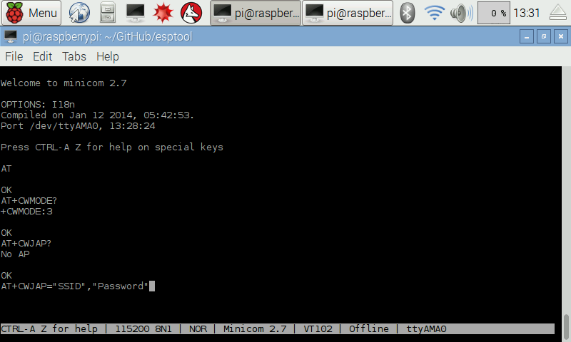
AT+CWMODE?
... followed by 'Enter' and then 'Control-J'.
(we won't be repeating that again, we're sure you got the point).
The answer you'll receive indicates how the ESP chip is currently configured to operate over WiFi: station mode (mode 1) is similar to laptops and phones in your network. When in this mode, the board will not broadcast an SSID and will require you to specify one that it can join. In Access Point mode (mode 2), however, the board will behave more like a router and will broadcast its own SSID so that your laptop or phone can join in.
The default, mode 3, is a combination of the two modes explained above (technically it will act similarly to a network repeater). It's OK to leave the ESP IoT pHAT in this mode for now, but check the summary of useful AT commands at the end of this tutorial if you wish to or need to alter the WiFi mode of the board.
If your IoT pHAT is brand new, or was recently factory reset or flash upgraded, it won't be part of any network nearby... yet. Still, you may want to query the current status before we go any further with the following command:
AT+CWJAP?
You'll likely receive a response stating that there is no AP (Access Point). In other words, the ESP is indeed not connected to your WiFi. Let's do that then!
AT+CWJAP="SSID","Password"
Of course, you should replace the SSID and Password values with your own. You may also probe your environment for all public SSIDs:
AT+CWLAP
Either way, if you receive no message to the contrary you should now be connected to your chosen network!

Checking WiFi status
Right let's reset the board and check that everything is still working. This is not strictly required, but it will demonstrate the persistence of your WiFi settings after a power cycle - meaning the board will always try to auto-connect to your network, if it can, on booting up. You can reset the board using the following AT command:
AT+RST
Then, reissue the query described earlier:
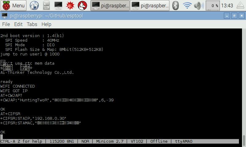
AT+CWJAP?
You should now see details about the network you chose to join! And, by issuing the following command, you'll get valuable information such as the current IP and MAC address of the ESP:
AT+CIFSR

Polling I/O values via serial
Ok, you've learned how to connect to a network but, unless you know how to poll the chip, that's not much good. We're now going to show you how to do just that, using AT commands.
Note that since we'll be querying data over serial, locally, this has obviously little to do with the networking aspect of the ESP, but together they'll eventually allow you to access your data remotely, though we won't discuss that in this tutorial.
Polling the I/O of the ESP8266 using AT commands is quite straightforward, if you know how. You may have noticed earlier that all the WiFI commands had one thing in common, AT+CW.... The good news is that all the IO commands also have something in common worth engraving in your memory: AT+CIO...
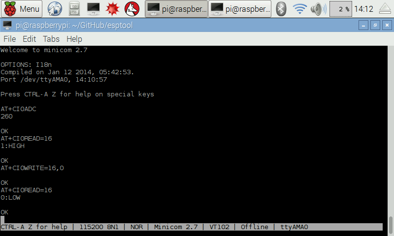
So, to probe an analog sensor attached to the ADC pin, you'd use:
AT+CIOADC
For the other GPIOs, as you might expect, you can both read and write the value, depending on whether you want to poll the status/access the value of an input, or wish to switch an actuator on or off:
AT+CIOREAD=16
or
AT+CIOWRITE=16,0
(if the READ command returned a LOW value for pin 16, issue AT+CIOWRITE=16,1 instead)
... feel free to verify you have indeed switched pin 16 from HIGH to LOW (or vice versa), by re-polling its status:
AT+CIOREAD=16
Easy, huh?
When ready, you can exit minicom with Control-A + Q.

Taking it further
That's all we have time for today, but we encourage you to practice your AT command skills until next time. Our journey into the exciting world of the ESP8266 is far from over and we'll show you many more ways to interact with your ESP IoT pHAT in the near future, not least to put its wonderful TCP/IP stack to good use.
I hope you enjoyed this overview of our most ambitious pHAT thus far - if you'd like to jump ahead, then head over to http://esp8266.com/, but do check back here regularly to see what we have in store for you!
Summary of useful AT Commands
AT - 'Hello World' (expected response is OK)
AT+RST - Reset chip
AT+GMR - Returns firmware information
AT+CWLAP - List Access Points details
AT+CWJAP? - Query Joined Access Point
AT+CWJAP="SSID","Password" - Join Access Point
AT+CWQAP - Quit Access Point
AT+CIFSR - Returns local IP and chip MAC address
AT+CWMODE? - Query WiFi Mode (1=STA, 2=AP, 3=AP+STA)
AT+CWMODE=1 - Set WiFi mode to Station mode
AT+CWMODE=2 - Set WiFi mode to Access Point mode
AT+CIOADC - Read value from Analog pin
AT+CIOREAD=pin - Read value from specified pin
AT+CIOWRITE=pin,0 - Write value 0 (LOW) to specified Digital pin
AT+CIOWRITE=pin,1 - Write value 1 (HIGH) to specified Digital pin
Search above to find more great tutorials and guides.