 Intermediate
Assembling your Picade
Build your own mini-arcade cabinet with this friendly, step-by-step guide to the latest Picade, designed for Raspberry Pi 5 with optional NVMe Base support.
This tutorial will help you assemble your 10" Picade, 2025 edition.
Checking your Picade version
Double check that you're following the correct assembly guide before you continue. Take a look at your Picade box. If you have a 2025 edition Picade, it will look like this - note the pink 'designed for Raspberry Pi 5' sticker!
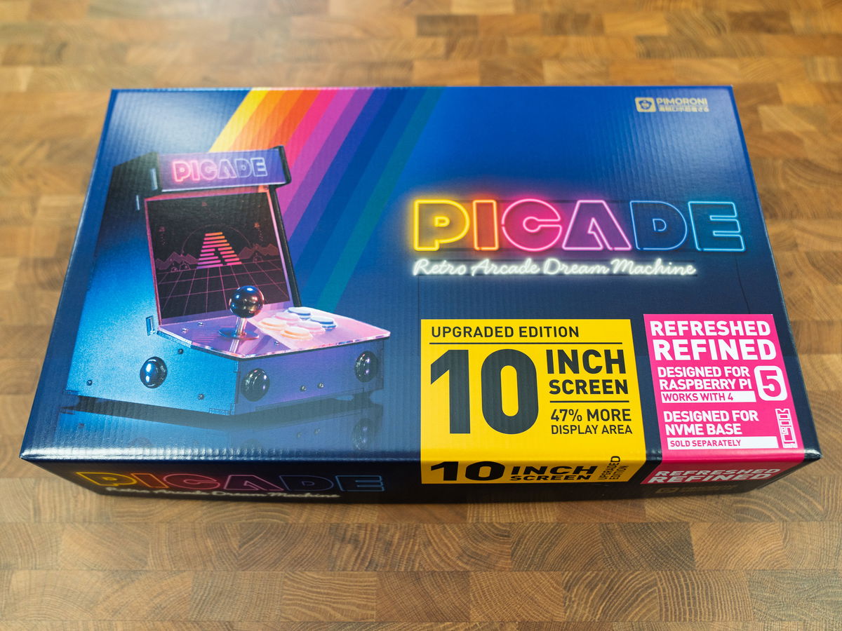
You can also identify a 2025 Picade from its console and marquee artwork - the art looks like this.

What you'll need
Essential
- A Picade kit!
You'll also need the following:
A Raspberry Pi 5. This version of Picade is designed to work nicely with Raspberry Pi 5, but if you want to use an older Pi with this kit that's also possible, as long as it has a 40 pin header attached. Note that this kit comes with a micro-HDMI cable, so if your Pi has a full size HDMI connector you'll also need to pick up a standard HDMI cable to plug it in.
A USB-C power supply (make sure you pick the correct power supply for your region)
Nice to have
An Active Cooler to keep your Pi nice and cool.
A NVMe Base if you want to add some super fast solid state storage.
Preparation
It'll take two to three hours to build your Picade. A large space, like a table or floor, with a soft covering is an ideal build space. There's a couple of points where it's useful to have an extra, friendly, pair of hands on stand by. You’ll also need a Phillips/cross-head screwdriver and a small flat blade screwdriver (2.5mm or smaller). If you don't have those already, you might want to grab an iFixit driver kit - they're great and we use ours every day.
Contents of the kit
In the box, you'll find a poster / cheat sheet for PICO-8 (with your redemption code printed at the bottom), an envelope full of our best stickers and four smaller boxes that contain the CABINET, FIXINGS, SCREEN, and ACCESSORIES (you'll find the cabinet box underneath the other three!).
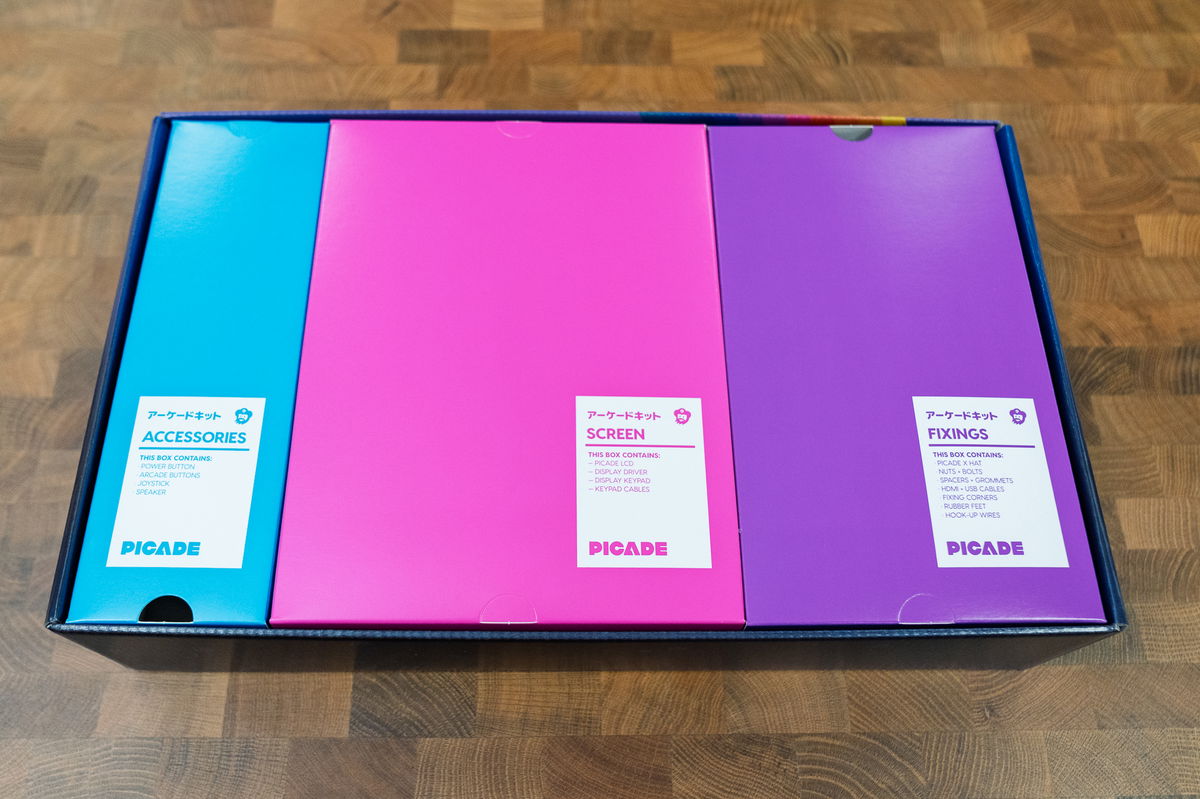
Here's a complete list of everything that's inside each box! If you're missing anything, drop us an email at support@pimoroni.com and we'll get it sorted.
CABINET box
- 6 powder coated wooden cabinet panels (marked A-F)
- Large square acrylic screen panel
- Printed cardboard screen surround
- Marquee assembly (comprising of two long acrylic pieces, and a 'Picade' printed cardboard insert)
- Console assembly (comprising of a wooden panel with holes for buttons, a matching acrylic piece and a printed cardboard insert)
SCREEN box
- 10" LCD screen panel
- 4 lasercut acrylic pieces for mounting the screen (marked 'Top 1' and 'Top 2' and 'Base 1' and 'Base 2')
- Screen driver board
- Screen keypad
- Long, thin ribbon cable for attaching driver board to keypad
- Short, wide ribbon cable for attaching driver board to screen
ACCESSORIES box
- Speaker
- Joystick
- Joystick ball
- Black plastic collar/dust cover for joystick
- Illuminated power button
- 10 arcade buttons (4 black, 2 blue, 2 yellow, 2 pink)
FIXINGS box
- Picade X HAT
- 9 L-shaped plastic brackets (for attaching the panels together)
- 4 rubber feet
- Rubber O ring
- HDMI to micro-HDMI cable
- USB micro B cable (for powering the screen)
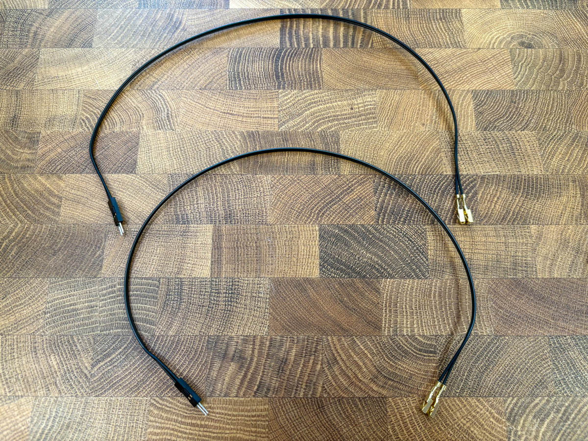
- Two Dupont to spade connector wiring looms (for plugging in the buttons)
- Joystick cable
- A bolt pack containing a bunch of nuts, bolts and threaded standoffs (we'll be using M2.5 and M3 bolts in this build)
- A booster header
- And a stylish pin badge!
Cabinet assembly
Cabinet assembly tips
First up, here's some general guidance to keep in mind throughout the build.
- The wooden panels are laser cut from MDF by us and then powder coated by a friendly, local Sheffield company. This process can result in some textural variation on the back of the panels and you might also notice some holes on the inside that don't go all the way through - these holes are where the panels are hung up to be powder coated. There should be an obvious good side and a 'label' side with markings and text on. The label side will always be on the inside of your Picade, so any patchiness on this side won't show once your Picade is assembled.
- The wooden panels are labelled A - F to help you identify them.
- Some parts of the cabinet assembly need there to be a bit of give in the cabinet, so it's a good idea not to tighten the screws and nuts that go through the brackets to fasten the wooden panels together fully until the end of the build.
- The heads of the screws should always be on the outside of your Picade cabinet, and the nuts/threaded ends of the screws should be on the inside.
- We laser cut the acrylic pieces in house at Pimoroni HQ (pew pew pew). They have a protective film on both sides that you'll need to remove as you fit the pieces to the cabinet. Note that the film may look a little bit different depending on what manufacturer we got that batch of acrylic from - some use opaque white film and some use translucent green film. Don't worry, the clear acrylic should look the same underneath!
Attaching the feet
For this section you'll need:
- Wooden panel A
- Rubber feet
To start, you'll need to find the square black wooden panel marked A in the CABINET box - this will become the base of your Picade. You'll also need the rubber feet, which are in the FIXINGS box.
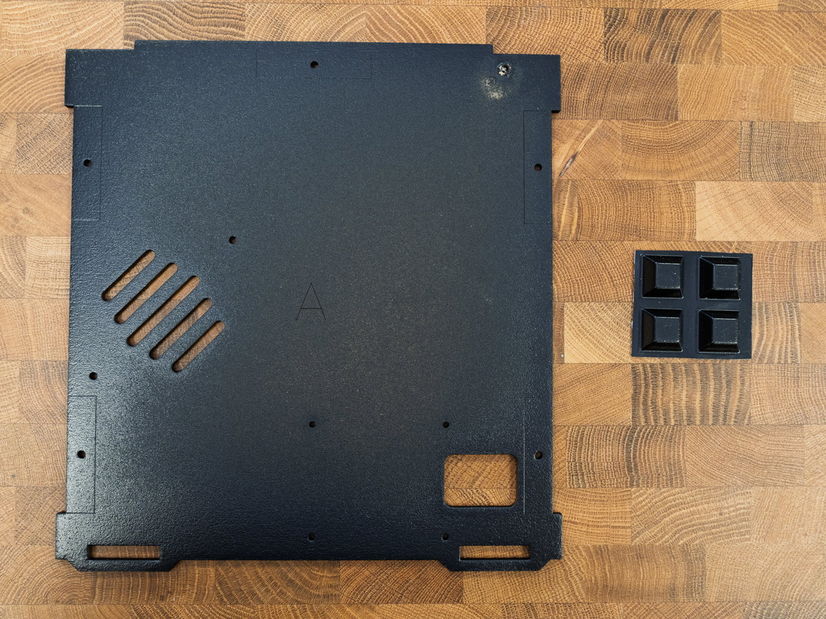
Flip panel A over so that the good side is on top.
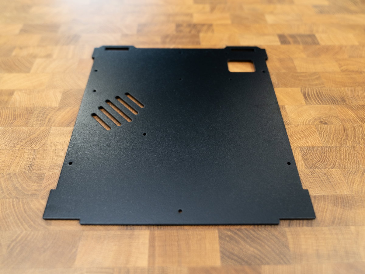
Then peel off the backing from the four rubber feet and stick them on the good side of the base, close to the corners. The tabs on the edges of the base will need to fit into slots later on, so make sure the feet aren't positioned right at the edges.
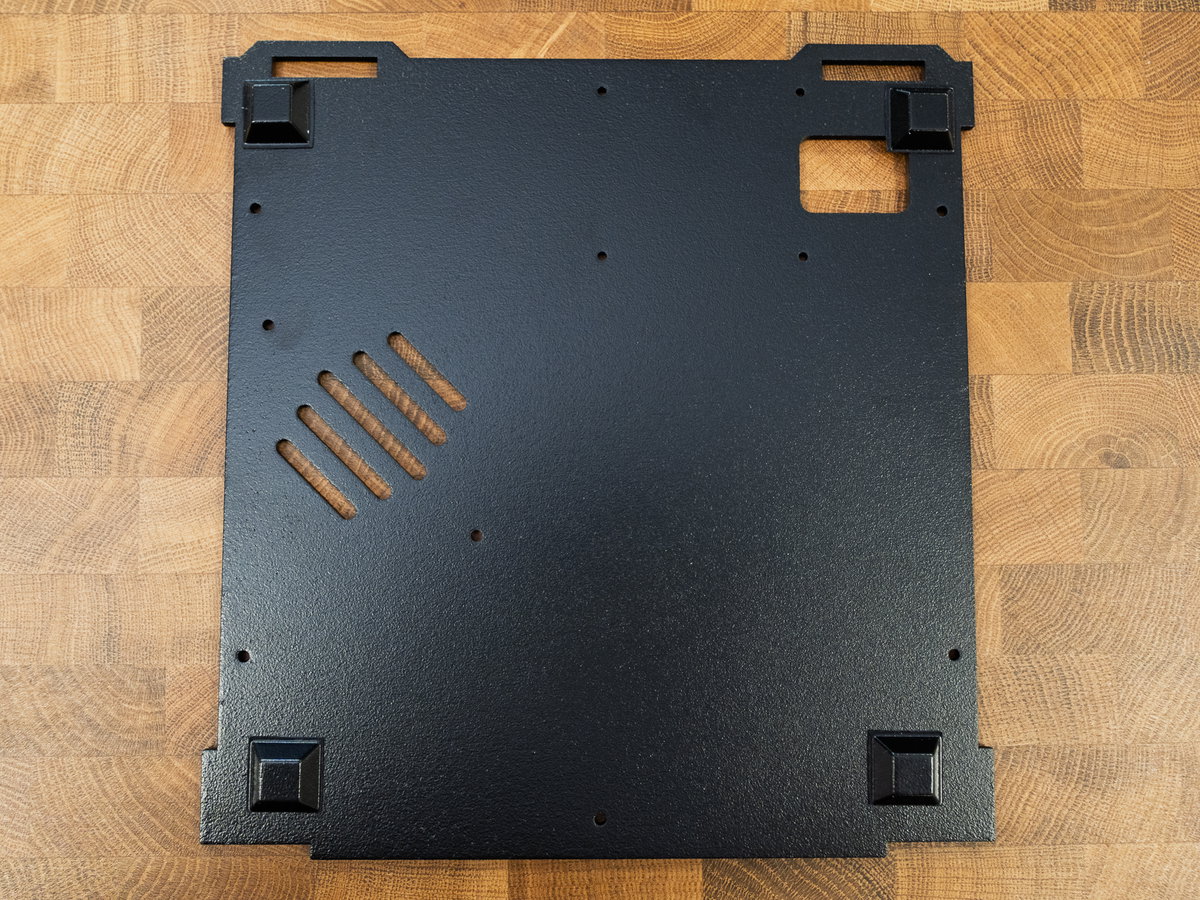
Now the base won't scratch your desk whilst you carry out the rest of the assembly!
Adding base brackets
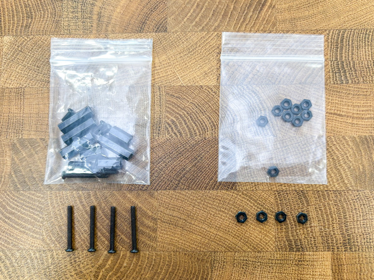
Open up the bolt pack and locate the bags of M3 12mm screws and nuts, they are the thicker ones and should look something like this.
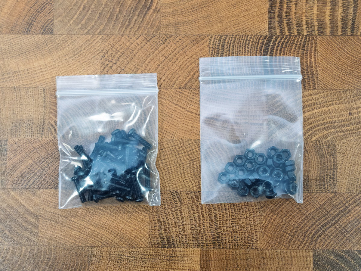
You'll use lots of these for fixing the cabinet together, and you'll want to always have them so that the heads of the bolts are on the outside and the nuts are on the inside of the cabinet (the side with the text labels on).
For the following section, you'll need:
- 5x L-shaped plastic bracket from the FIXINGS box
- 5x M3 screws
- 5x M3 nuts
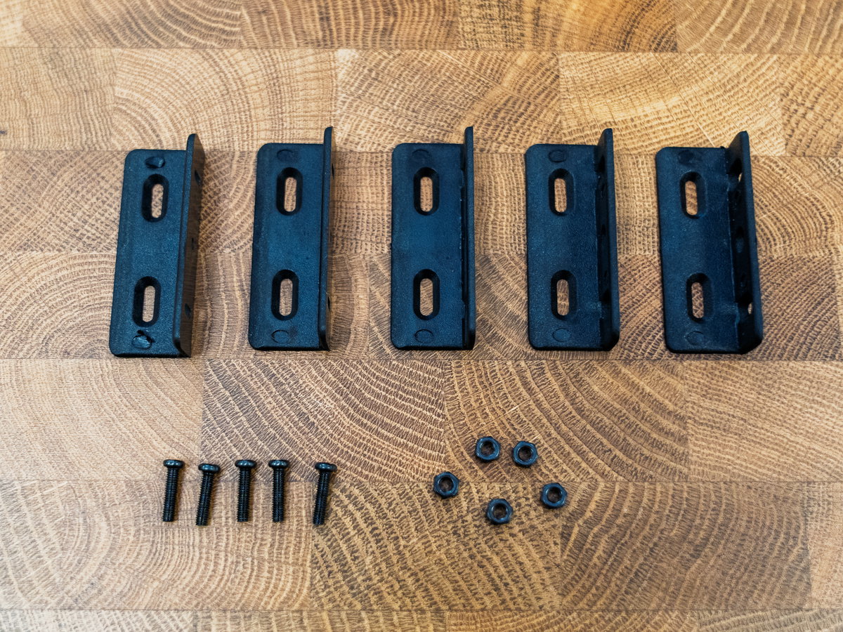
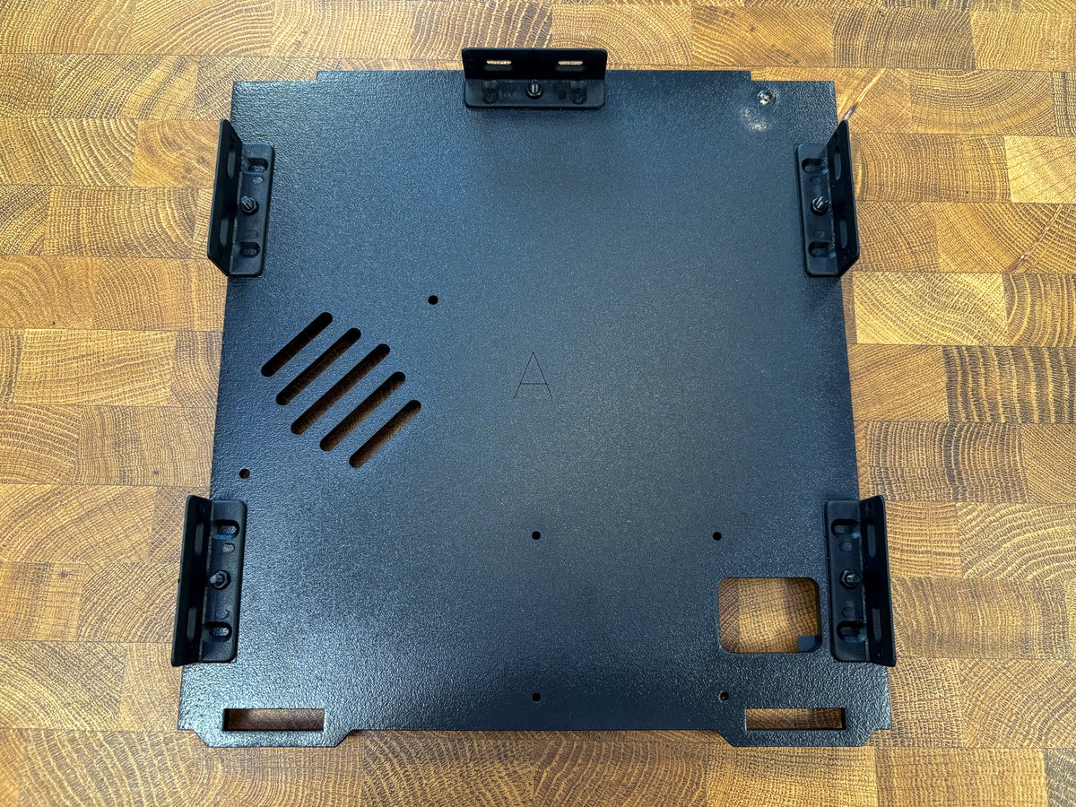
Flip panel A over so that it's standing on its feet. There are five rectangular outlines on the label side of panel A that show where to attach the brackets.
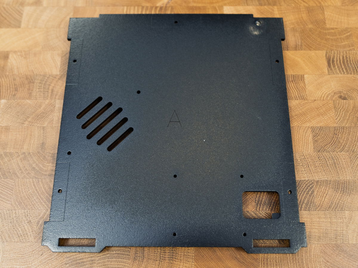
Push a screw through one of the bracket holes on Panel A from the underside.
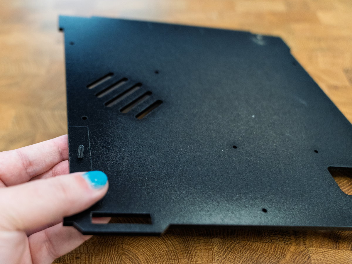
Then thread the bolt through the round, centre hole on the bracket - the round holes in the brackets can be a bit tight so you might need to use your screwdriver to get the screw thread to first engage.
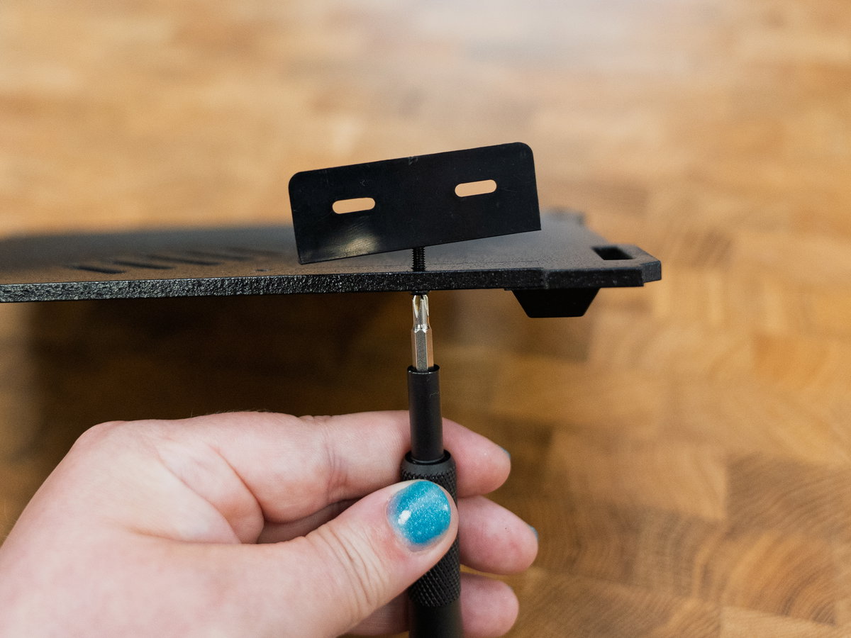
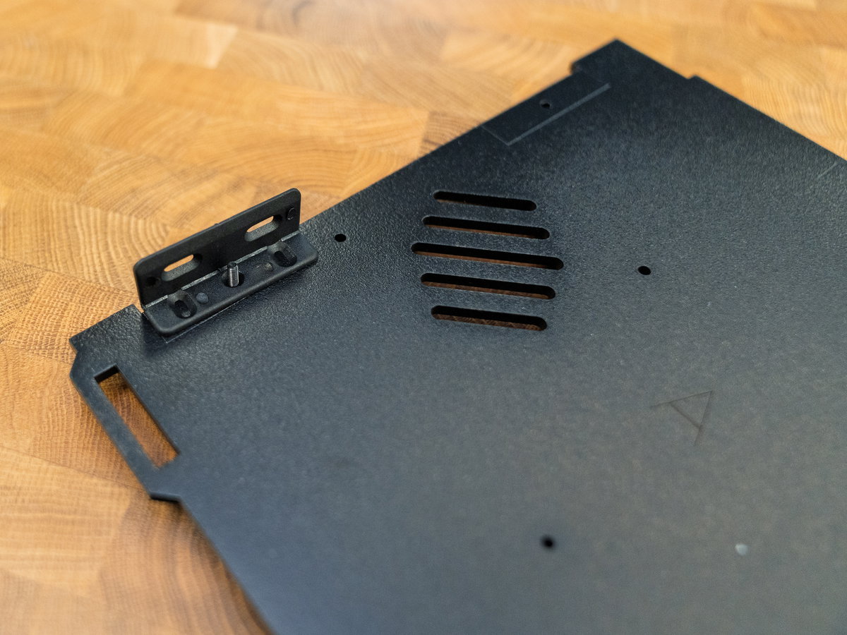
Fix the bracket in place with a nut.
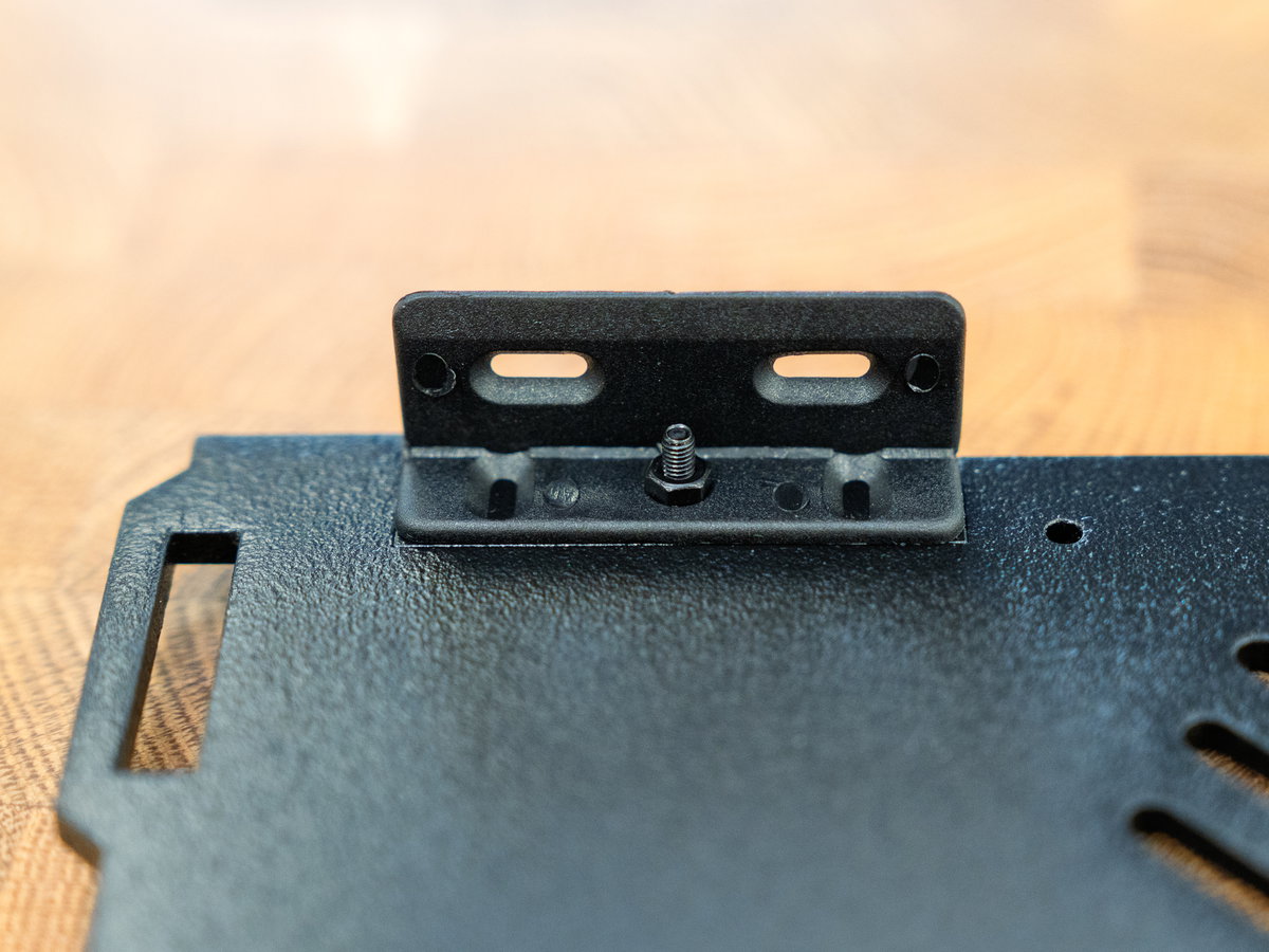
Repeat this process until you have five brackets attached to panel A.
Mounting your Raspberry Pi to the base (without NVMe Base)
Now it's time to attach your Raspberry Pi to panel A. If you're planning on just using an SD card for storage then you can follow the instructions in this section. If you're planning on installing an NVMe Base in your Picade skip this section and move onto the next one.
Locate:
- your Raspberry Pi
- your Active Cooler (it's fine if it's already attached to your Pi 5, you don't need to remove it).
- The bag that contains various lengths of M2.5 threaded standoffs (and an assortment of M2.5 bolts)
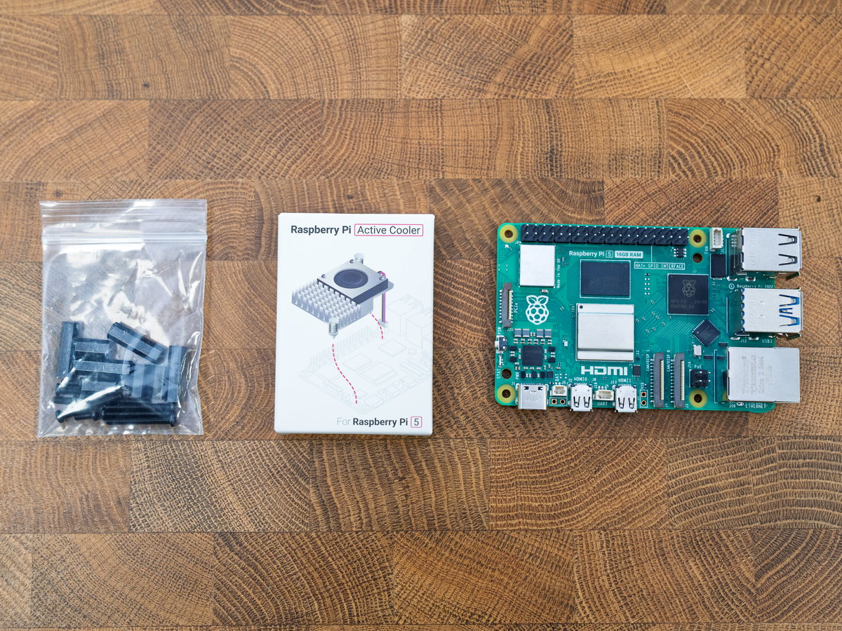
If you're using an Active Cooler and you've not attached it already, fit it to your Pi 5 now. If you need help with that, check out Raspberry Pi's documentation.
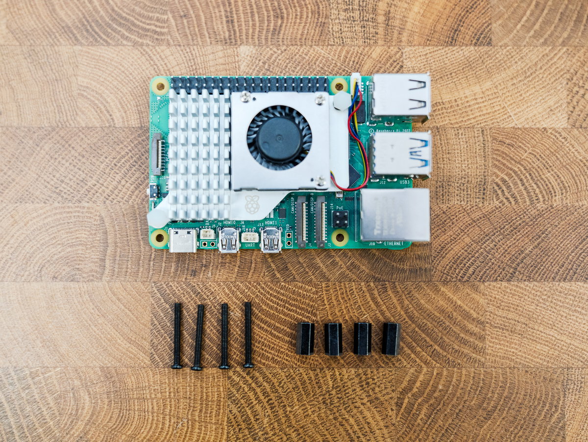
To complete this section you'll need
- a Raspberry Pi (with Active Cooler attached, if you're using one)
- 4x M2.5 20mm bolts (the longest bolts from the bag with the standoffs)
- 4x 10mm M2.5 standoffs (the shorter ones)
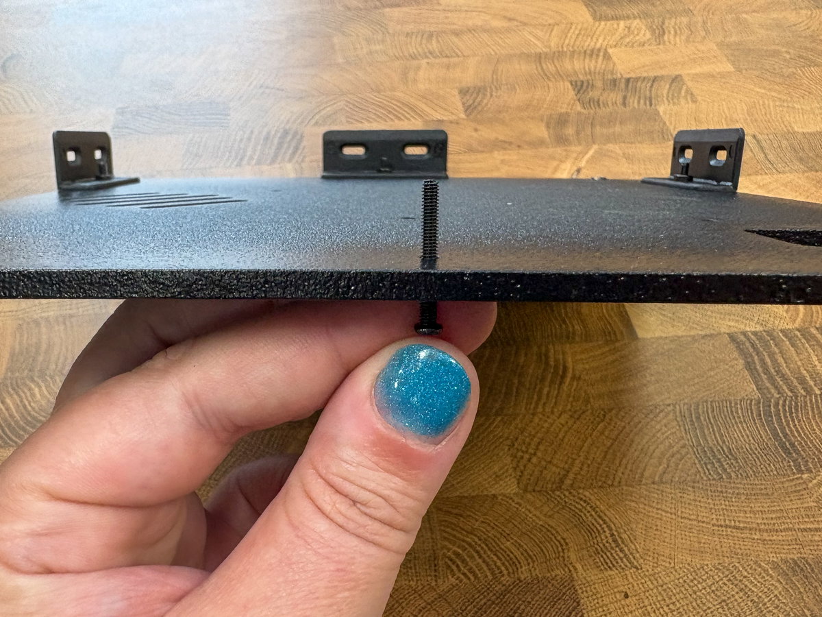
The four mounting holes for the Pi are located near a rectangular cutout that will let you access the Pi's SD card once everything's assembled. Poke one of the long bolts through one of the holes, from the bottom.
Then screw one of the 10mm standoffs onto the screw thread.
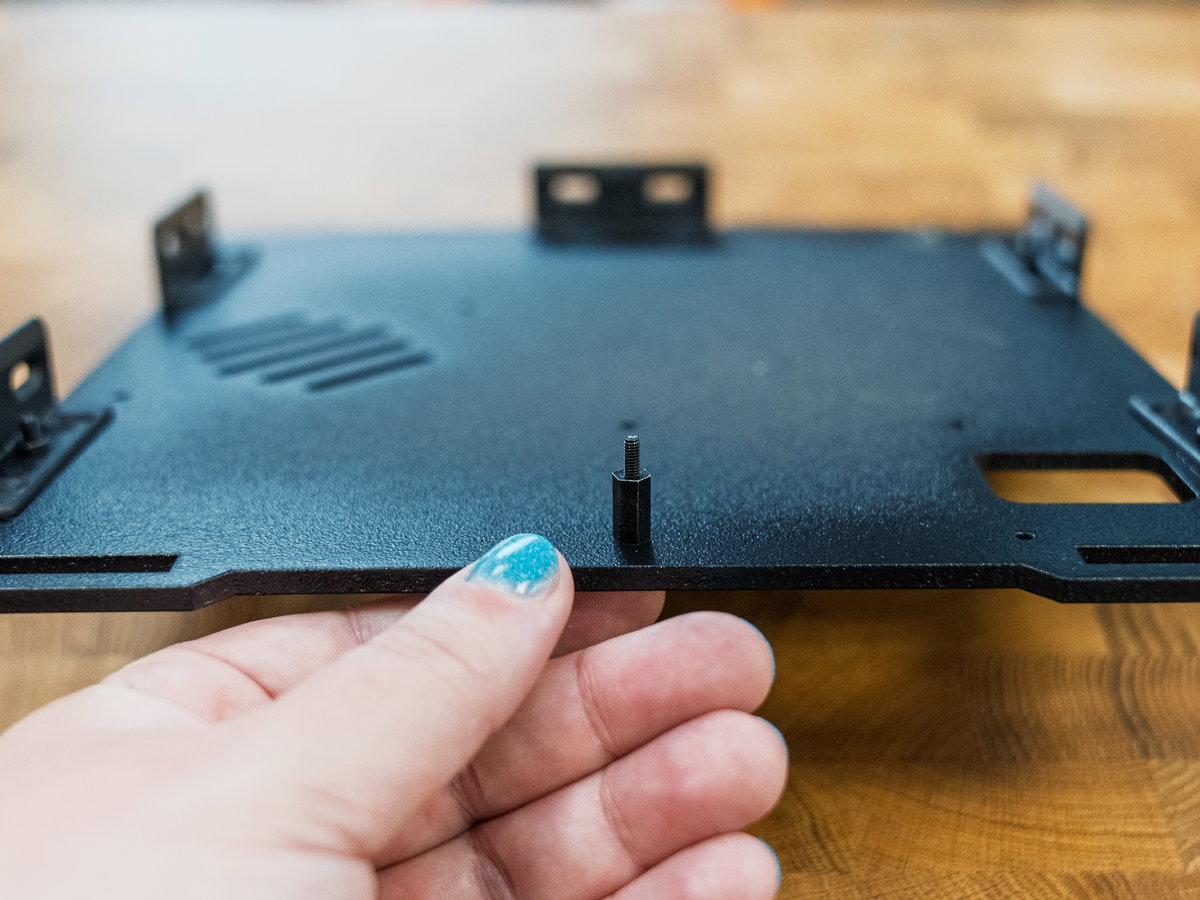
Repeat this process until you have all four standoffs attached to panel A.
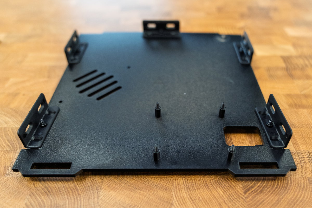
Place your Pi onto the bolts, with the Pi's SD card slot over the rectangular cutout.
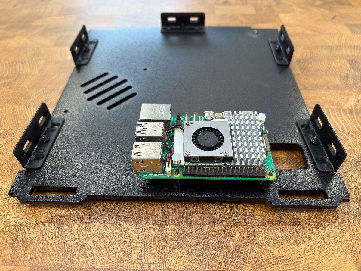
Mounting your Raspberry Pi to the base (with NVMe Base)
Here's how to incorporate an NVMe Base in your setup. Note that the Picade cabinet will only accommodate the single NVMe Base, not NVMe Base Duo.
If you're using an Active Cooler and you've not attached it already, fit it to your Pi 5 now. If you need help with that, check out Raspberry Pi's documentation.
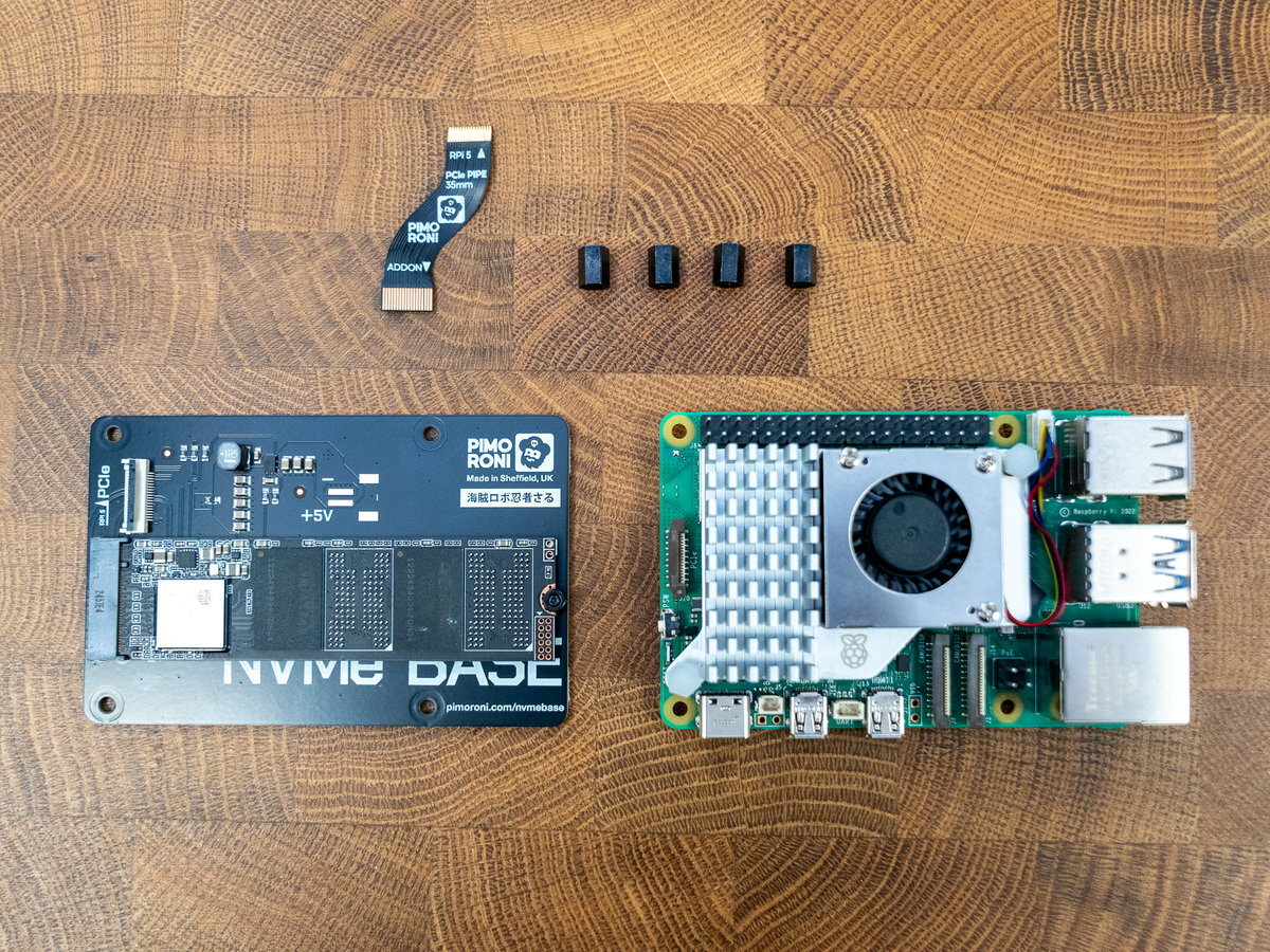
You'll also need to attach your SSD to the NVMe Base before continuing. Full instructions for assembling NVMe Base can be found here, if you need them. Note that you don't need to fit the standoffs, plug in the ribbon cable or attach the feet.
To complete this section you'll need:
- a Raspberry Pi (with Active Cooler attached)
- An NVMe Base with SSD installed
- a PCIe ribbon cable (this comes with NVMe Base)
- 4x 7mm M2.5 standoffs (these also come with NVMe Base)
From the Picade bolt pack, you'll need:
- 4x M2.5 20mm bolts (the longest bolts from the bag with the threaded standoffs)
- 4x M2.5 nuts (ours were in their own bag)
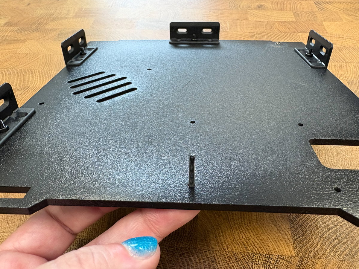
The four mounting holes for the Pi are located near a rectangular cutout that will let you access the Pi's SD card once everything's assembled. Poke one of the long bolts through one of the holes, from the bottom.
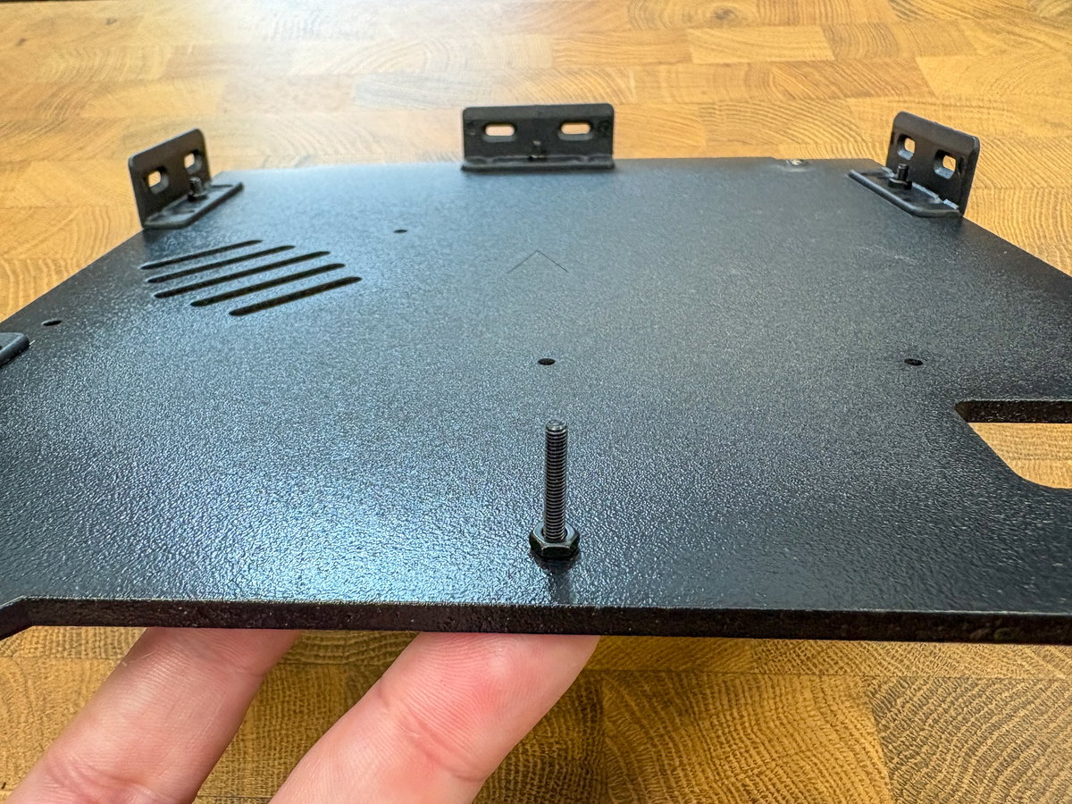
Then screw one of the nuts onto the screw thread.
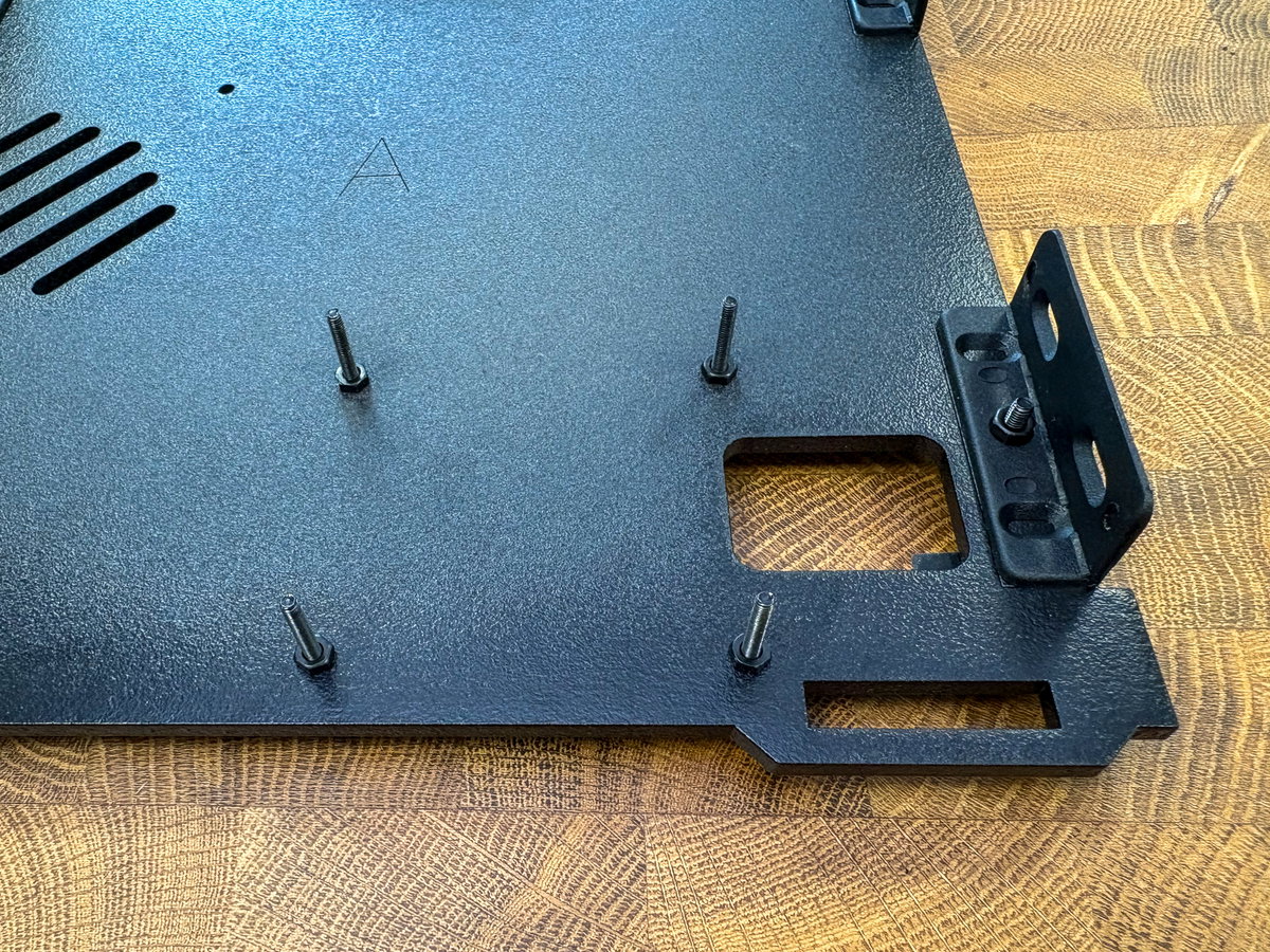
Repeat this process until you have all four bolts and nuts attached to panel A.
Once the SSD is fastening in place, slot the NVMe Base over the screw threads. The PCIe connector should be on the top side and next to the rectangular cutout in panel A.
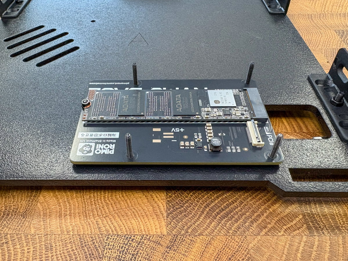
Then fix it in place with the 7mm standoffs.
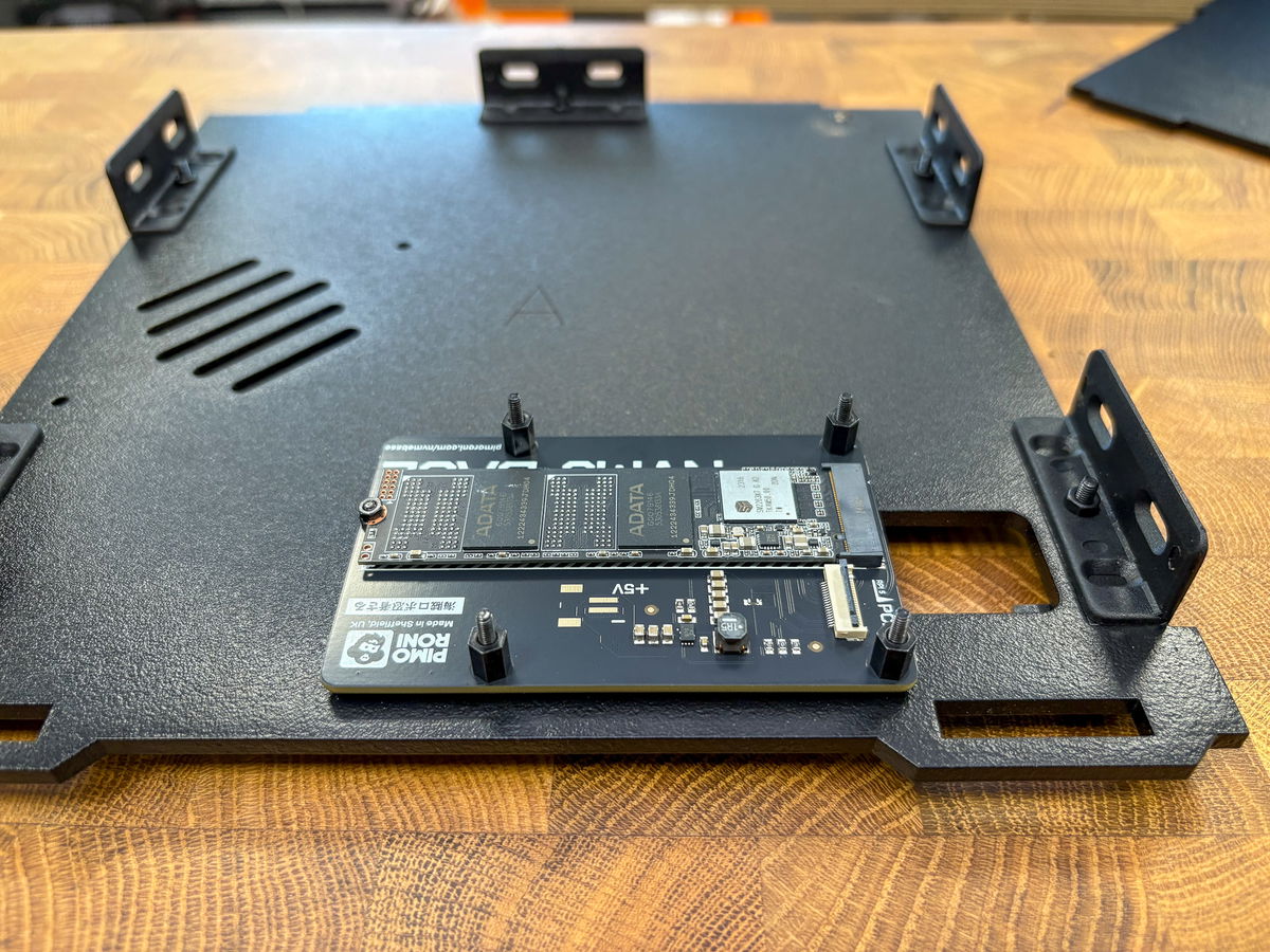
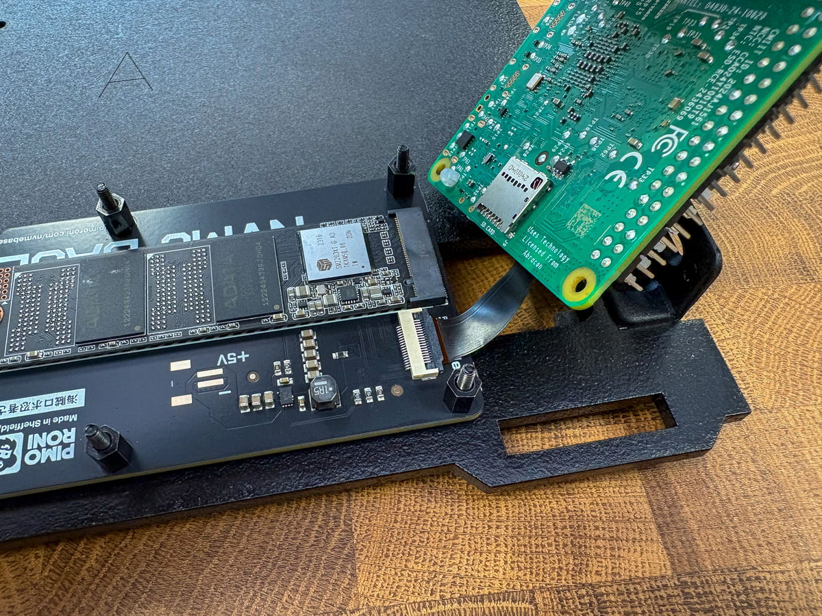
Plugging in the PCIe ribbon cable is a bit fiddly, and you might find tweezers helpful for this part. We found it easiest to plug it into the Pi first...
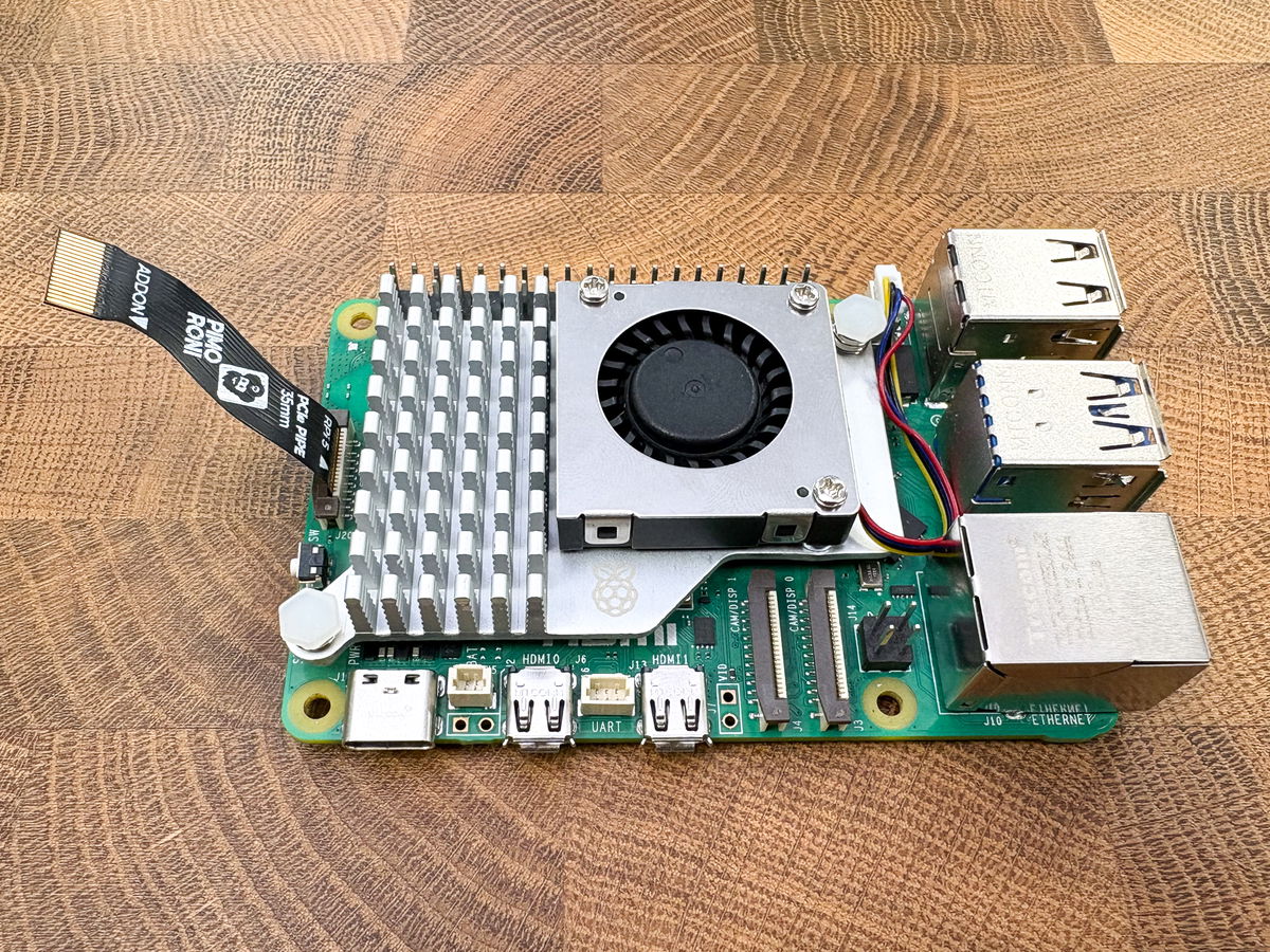
...and then plug it into the connector on the NVMe base.
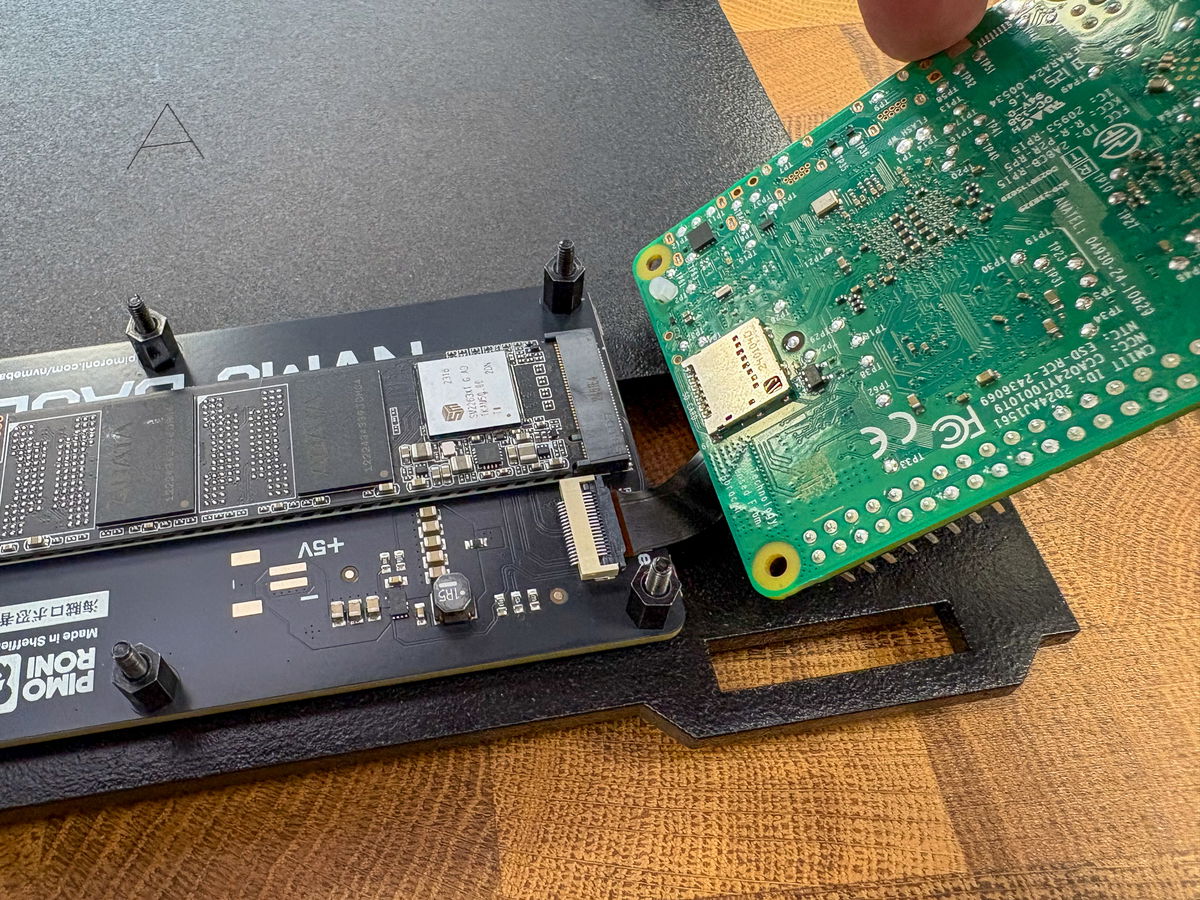
Once both boards are connected, you can turn the Pi the correct way up and sit it on top of the screw threads. Be careful when doing this not to dislodge / damage the cable.
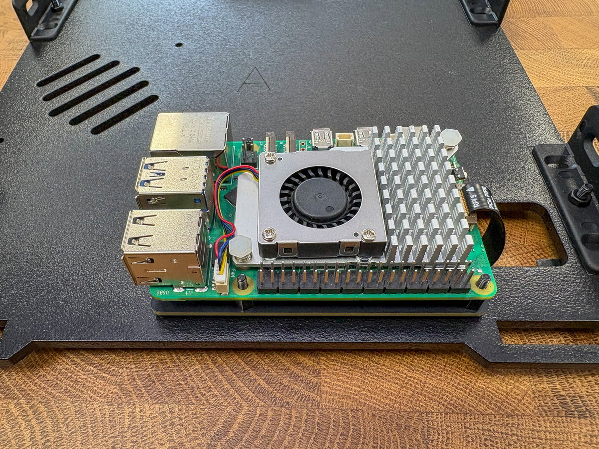
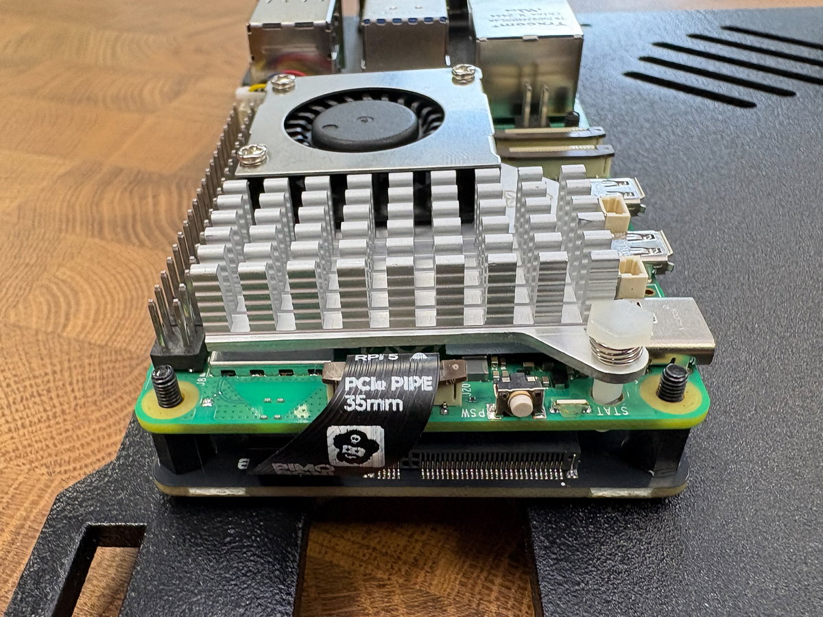
Now is a good time to check that the orientation of everything is correct. The PCIe cable should be next to the rectangular cutout on panel A, and the writing on the cable should be visible.
Mounting the Picade X HAT
Next we'll be adding the Picade X HAT to the top of our stack, so we can connect up all those lovely inputs later on.
You'll need:
- Picade X HAT
- Booster header
- 4x 17mm M2.5 standoffs (the longer ones from the bag of standoffs)
- 4x M2.5 6mm bolts (also from the bag containing standoffs)
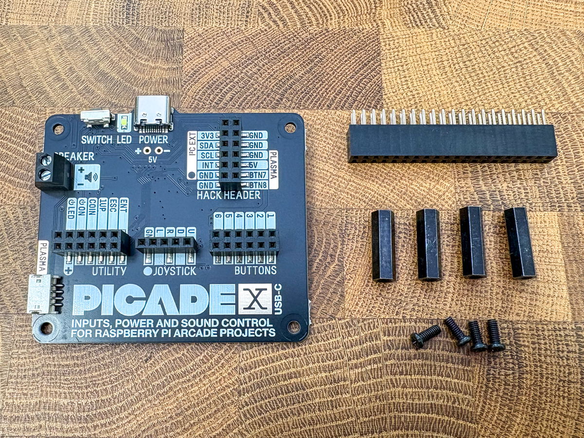
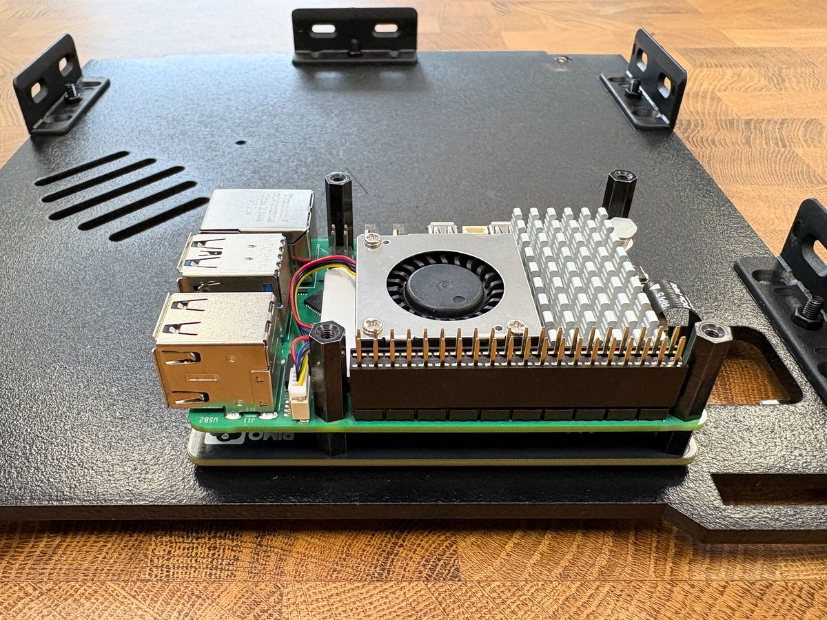
Push the booster header down onto the Pi's GPIO pins (make sure it's correctly lined up and not 'off by one'). Then screw the long 17mm standoffs onto the screw threads.
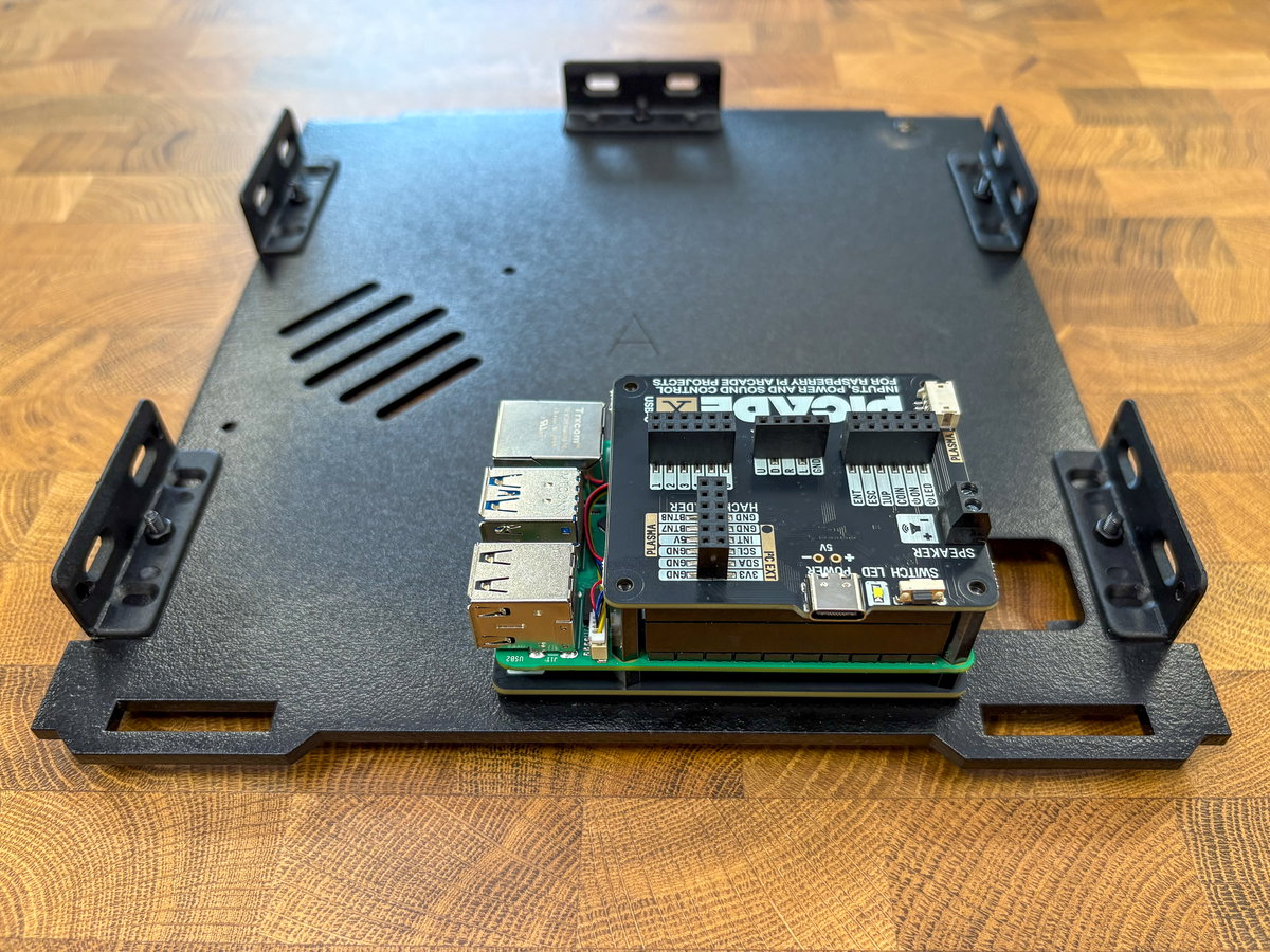
Now push the Picade X HAT onto the Pi's GPIO pins, ensuring that the pins are correctly lined up and the holes line up with the standoffs.
Use four of the smaller metal M2.5 screws to secure the HAT to the standoffs.
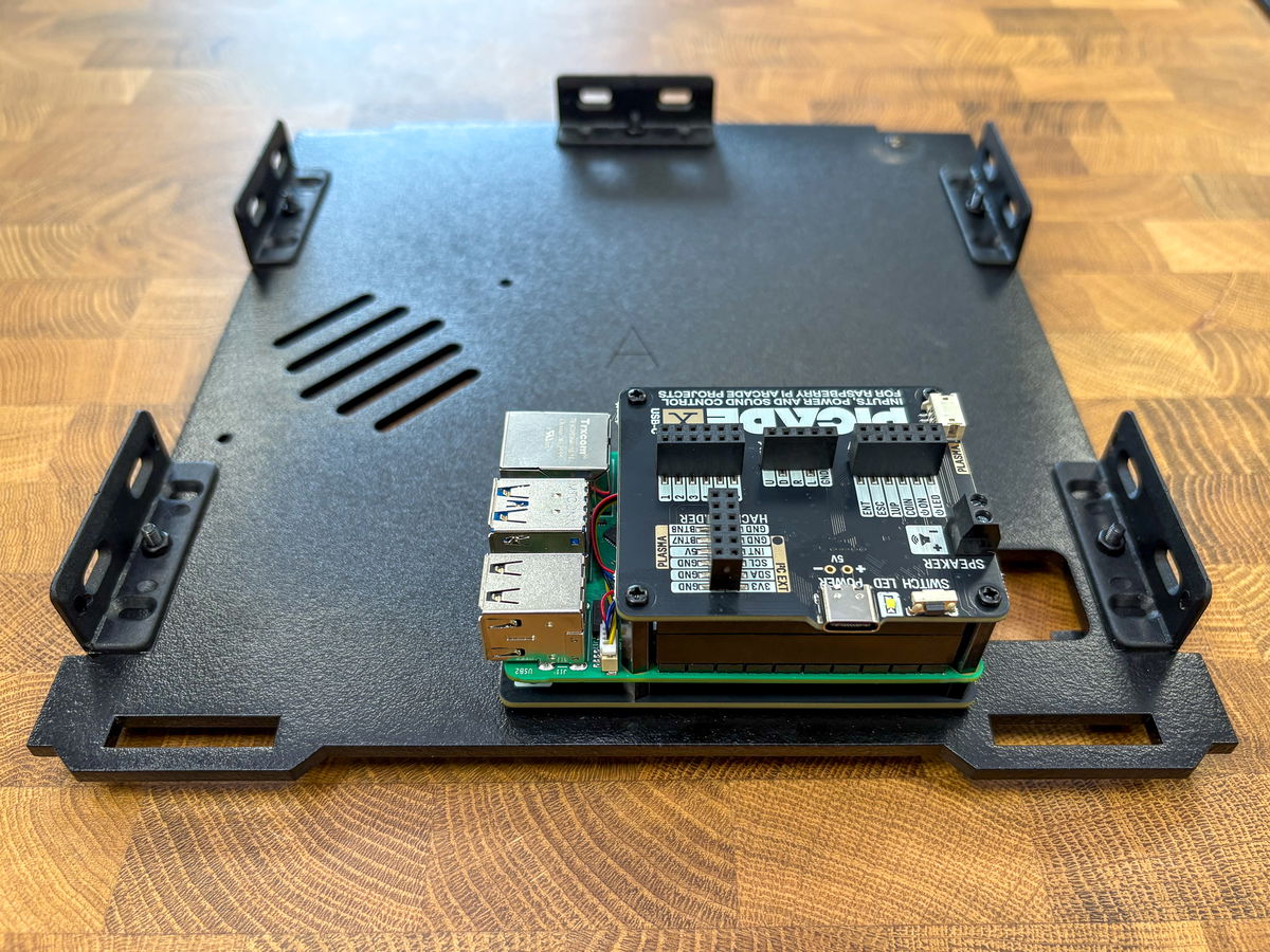
Stack complete!
Attaching the speaker
Next you'll need:
- Speaker
- 2x M3 bolts
- 2x M3 nuts
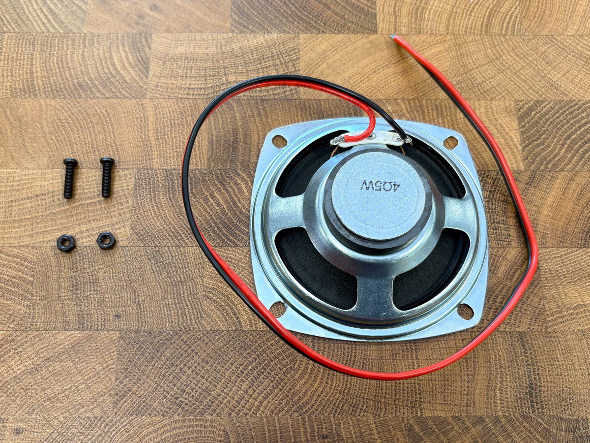
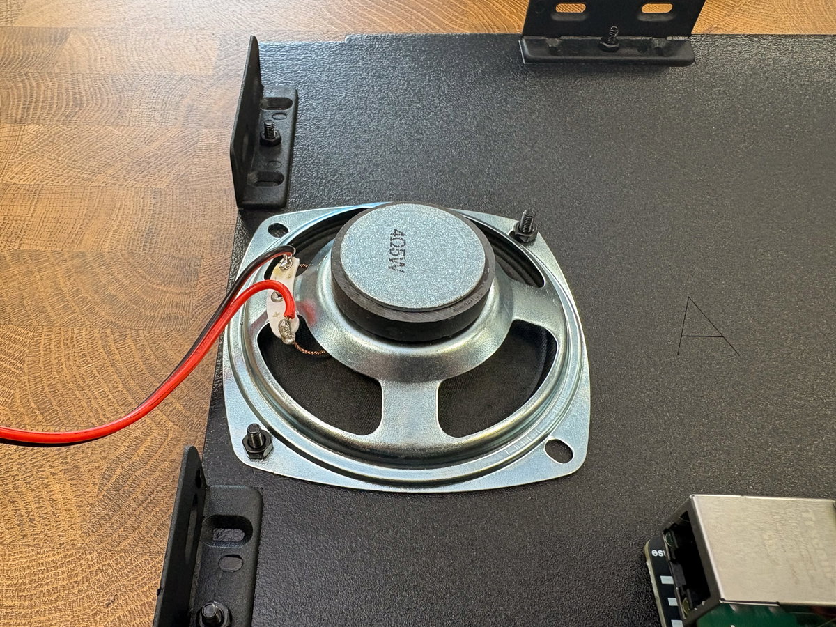
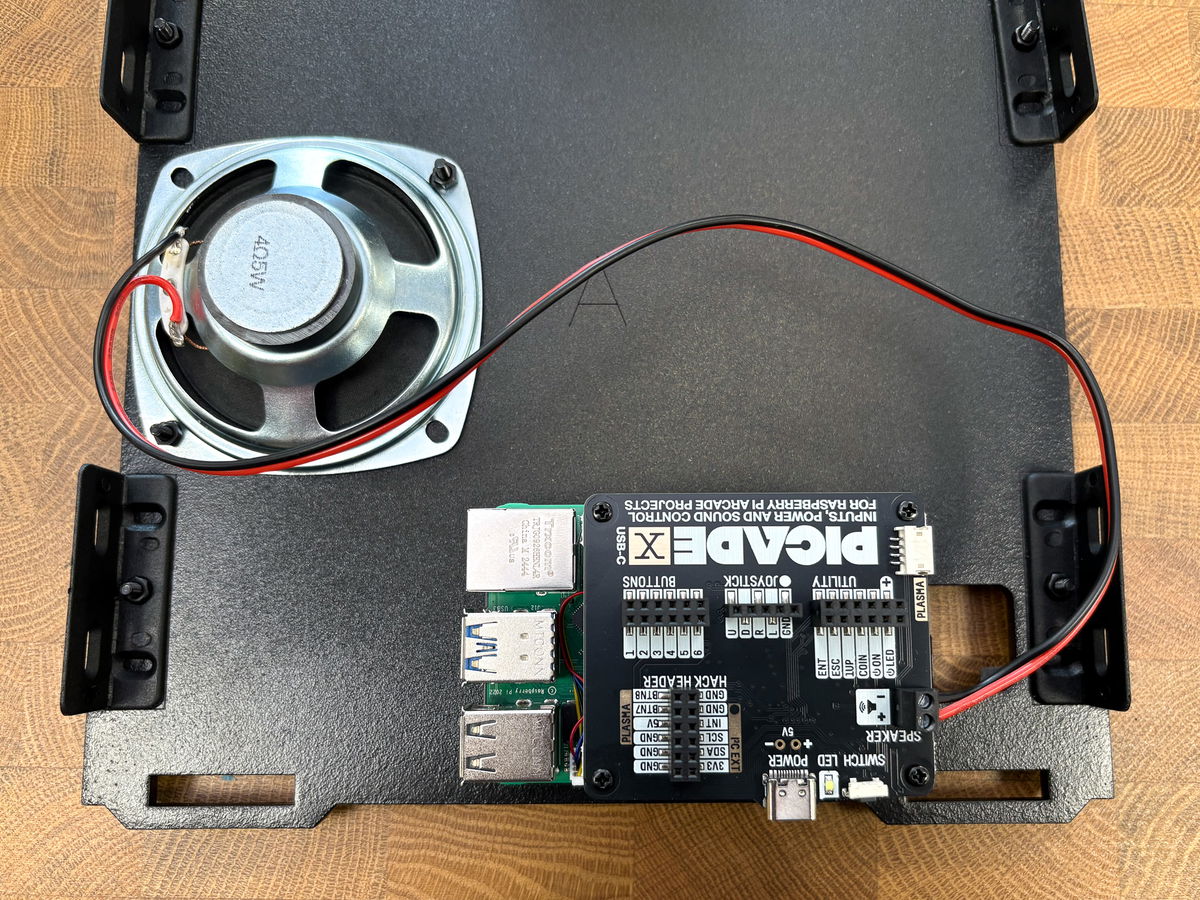
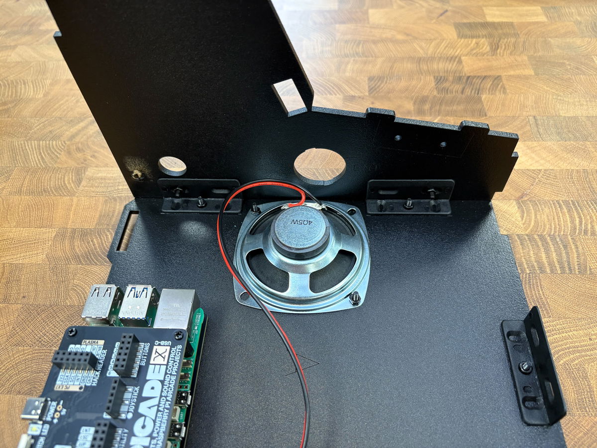
Place the speaker on the label side of panel A, with the paper cone against the cutouts and the wire pointing towards the edge of the Picade. Secure it with M3 screws, pushed through from the good side, and M3 nuts. The paper cone of the speaker is delicate, so take care not to accidentally damage it.
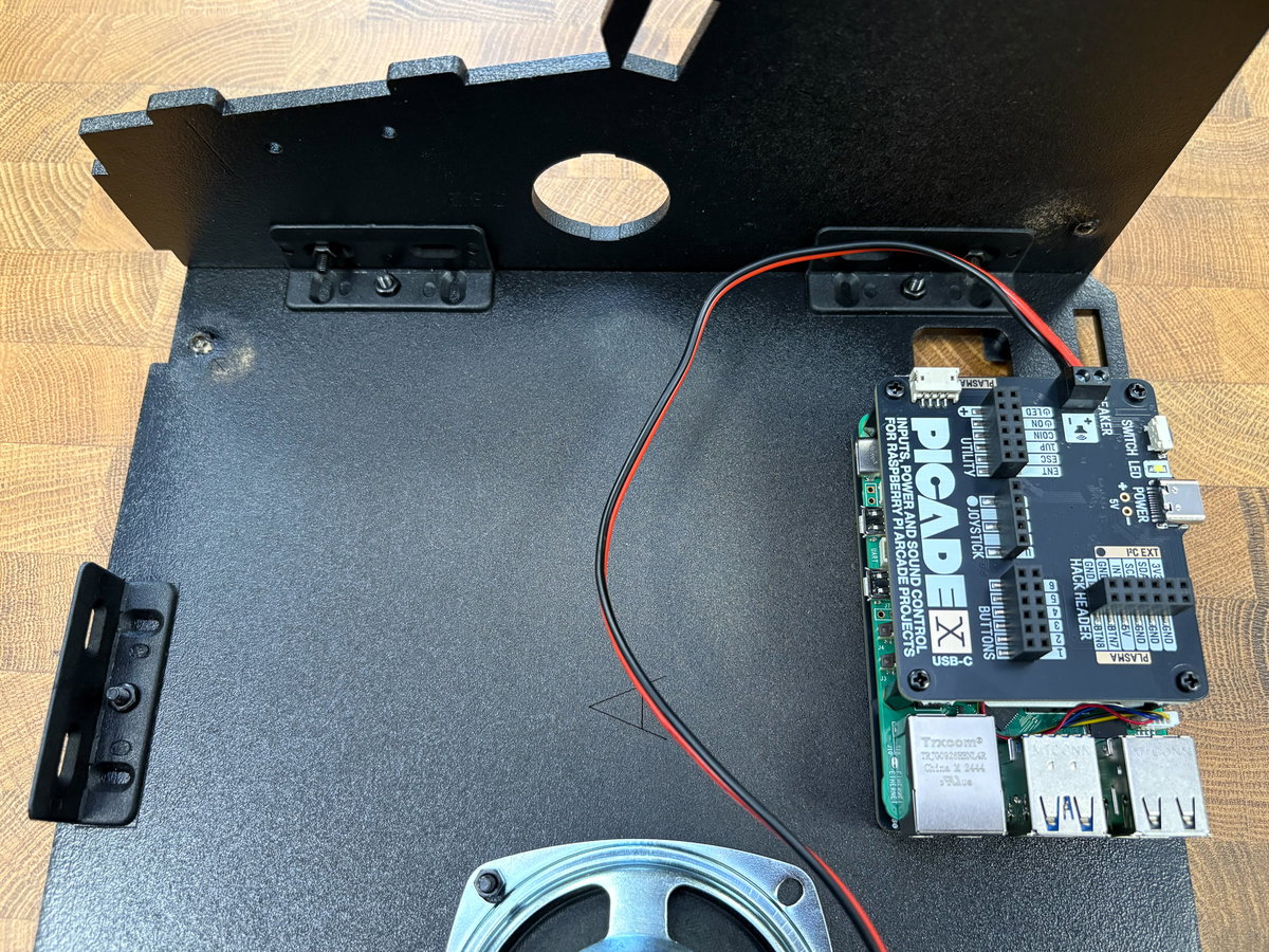
The speaker wires connect to the screw connector on Picade X HAT, marked SPEAKER.
One at a time, loosen the screw terminals with a small flat head screwdriver and slot in the wires, matching red to + and black to -. Then tighten up the screws and give the wires a little tug to make sure they're securely anchored in the terminals.
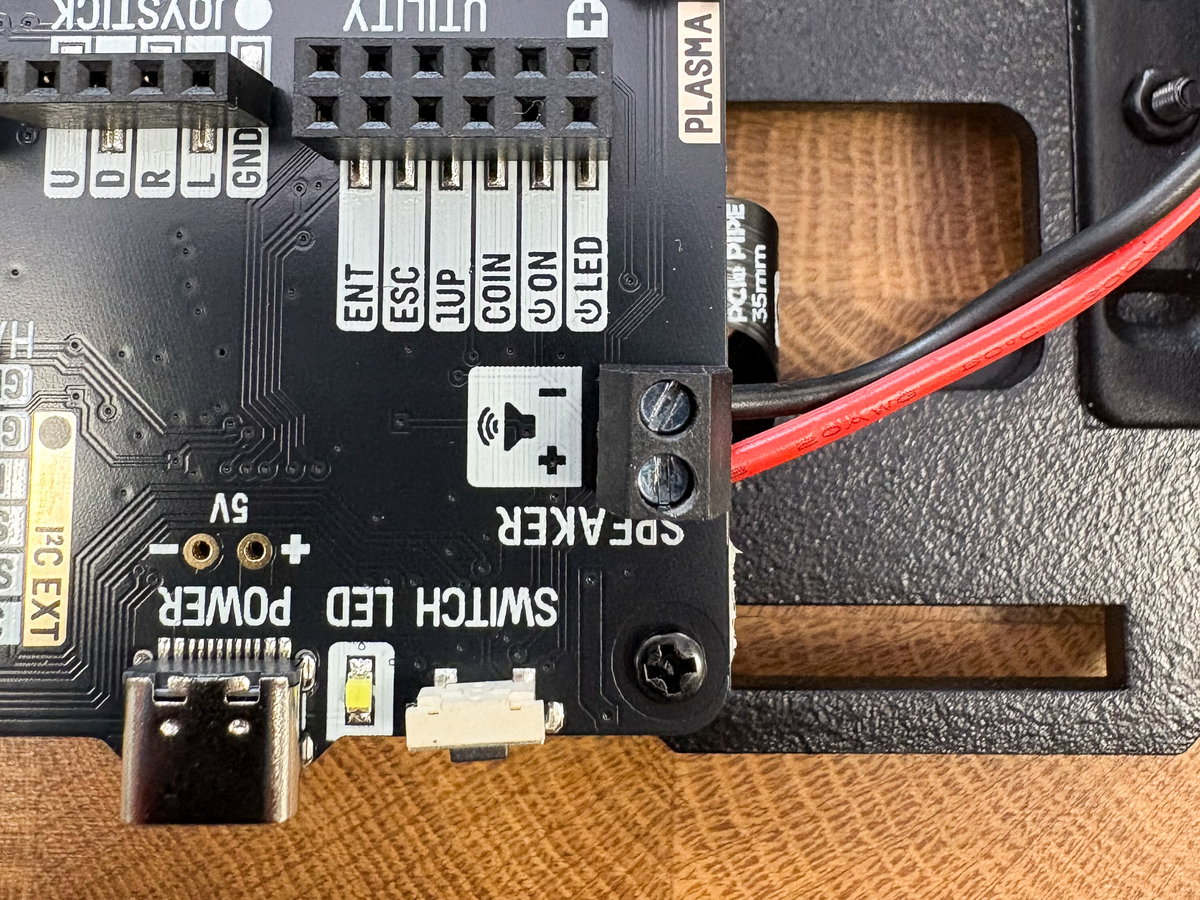
Double check that the screw terminals are gripping the metal core of the wires, not onto the insulation surrounding them!
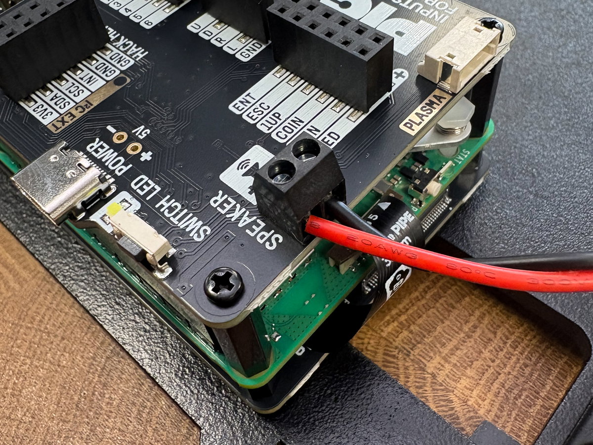
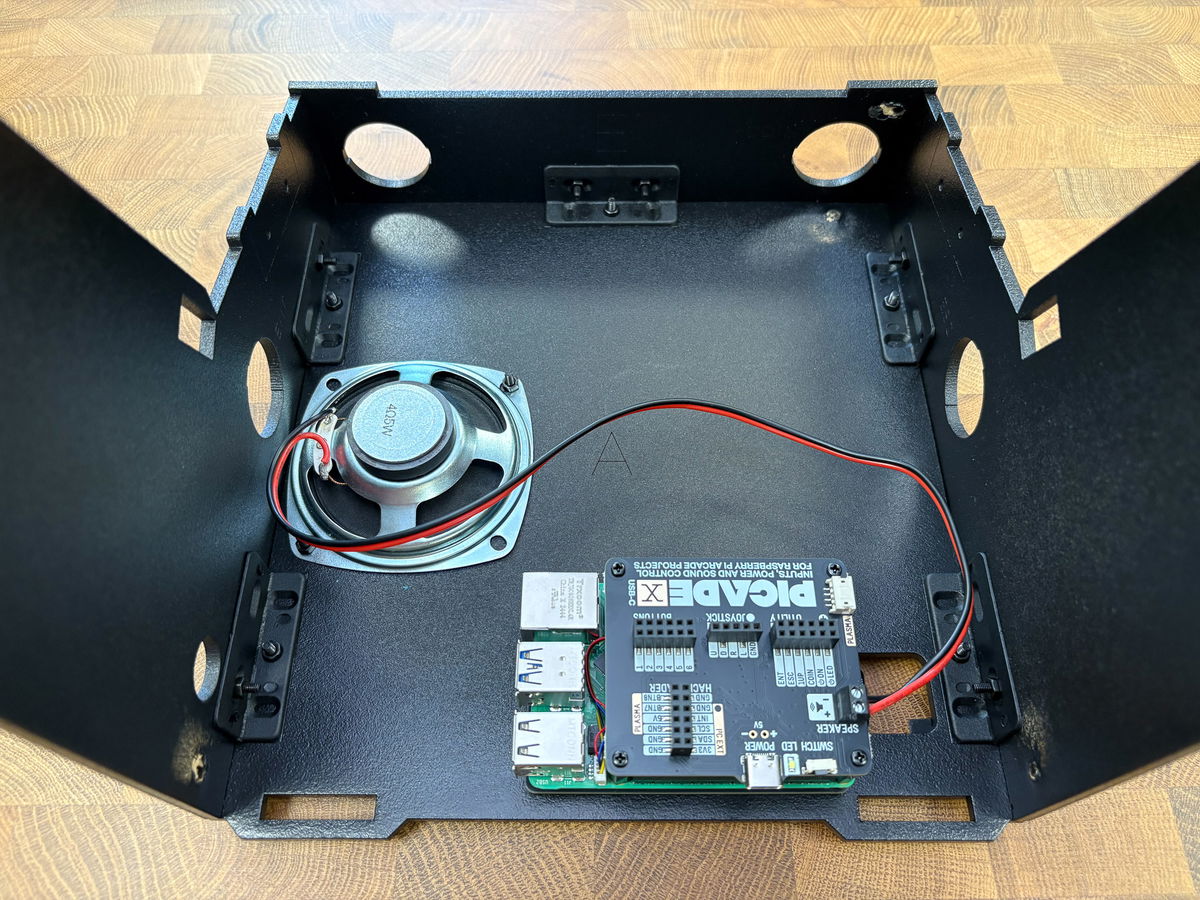
Here's what things should look like so far.
Attaching the sides and front
For this step you'll need:
- Wooden panel B
- Wooden panel D
- Wooden panel E
- 6x M3 bolts
- 6x M3 nuts
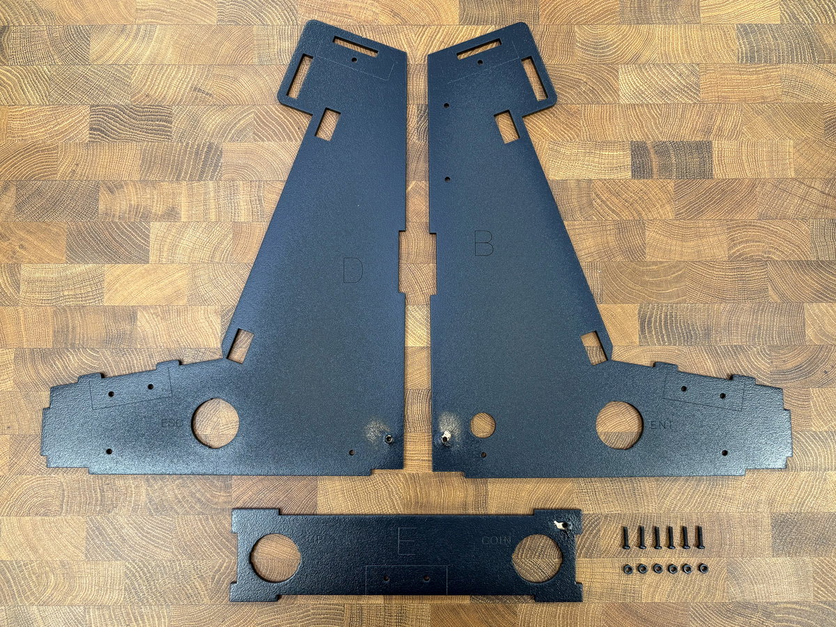
Locate wooden side panel B and attach it to the two brackets on the side of the base closest to the speaker grill, using two more M3 nuts and bolts pushed through from the outside.
Attach wooden side panel D to the opposite side of the base in the same way.
Panel E is the front of the cabinet, and it slots between the short edges of the side panels (the tabs should fit neatly into the slots). Make sure the two little holes are at the bottom edge of this piece, next to the base. Secure the front in place with two M3 bolts.
Adding the top brackets
We won't be fitting the top just yet, but we can add the brackets for when we do. You'll need:
- 2x L-shaped plastic brackets
- 2x M3 screws
- 2x M3 nuts
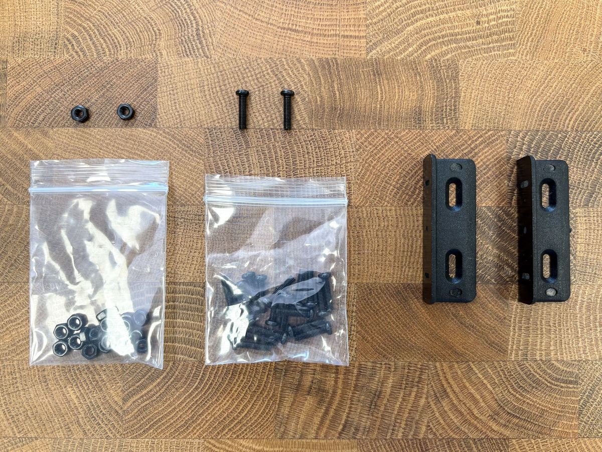
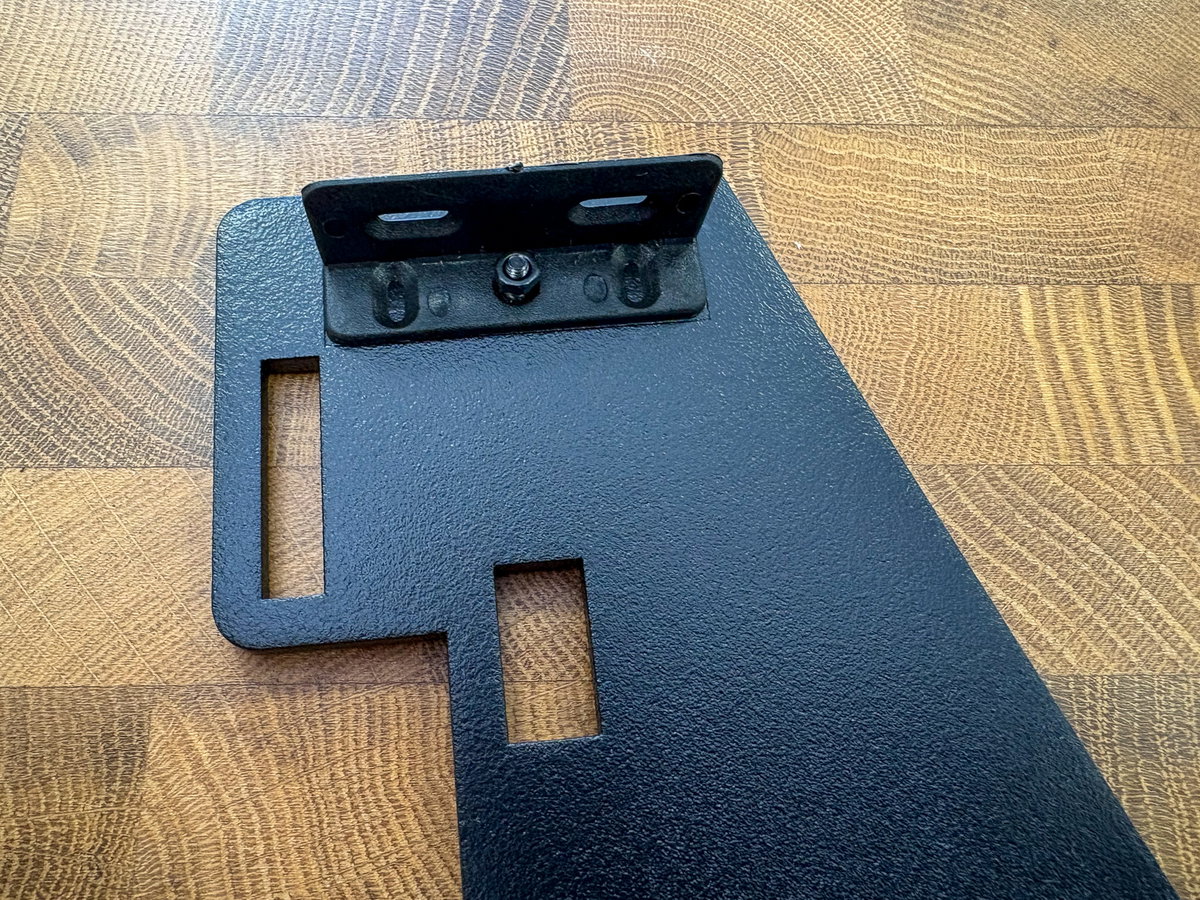
Attach the brackets inside the outlines at the top of side panels B and D, using the single hole.
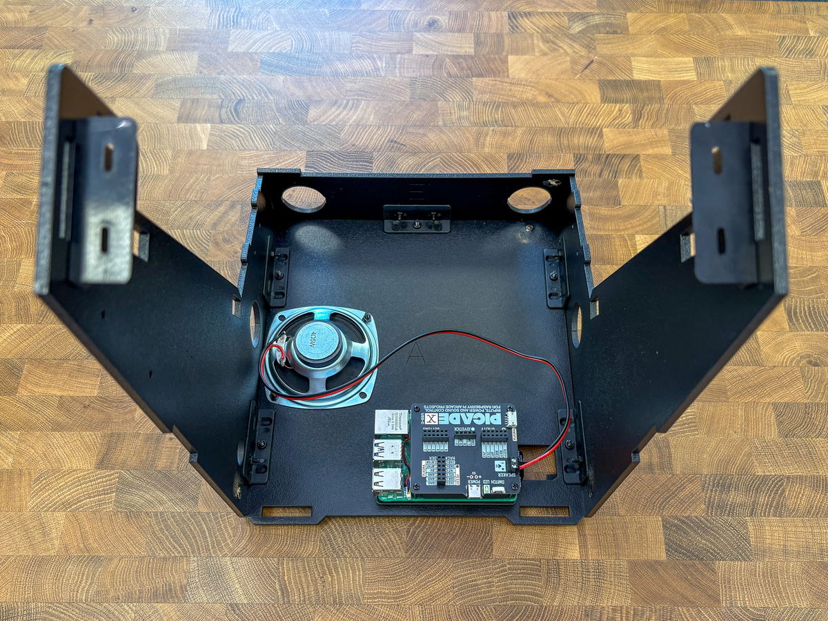
You can set the cabinet aside for now - here's what ours looks like so far. You're now about a third of the way through the build, so now's a good time for a break.
Building the screen assembly
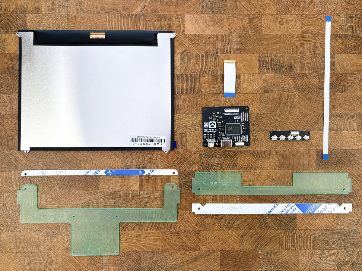
Next job is to put the screen assembly together. You'll need the contents of the SCREEN box:
- the 10" LCD screen
- the screen driver board
- a short ribbon cable with a gold bit on the end (this is used to attach the driver board to the screen)
- a long thin ribbon cable (this is used to attach the driver board to the keypad)
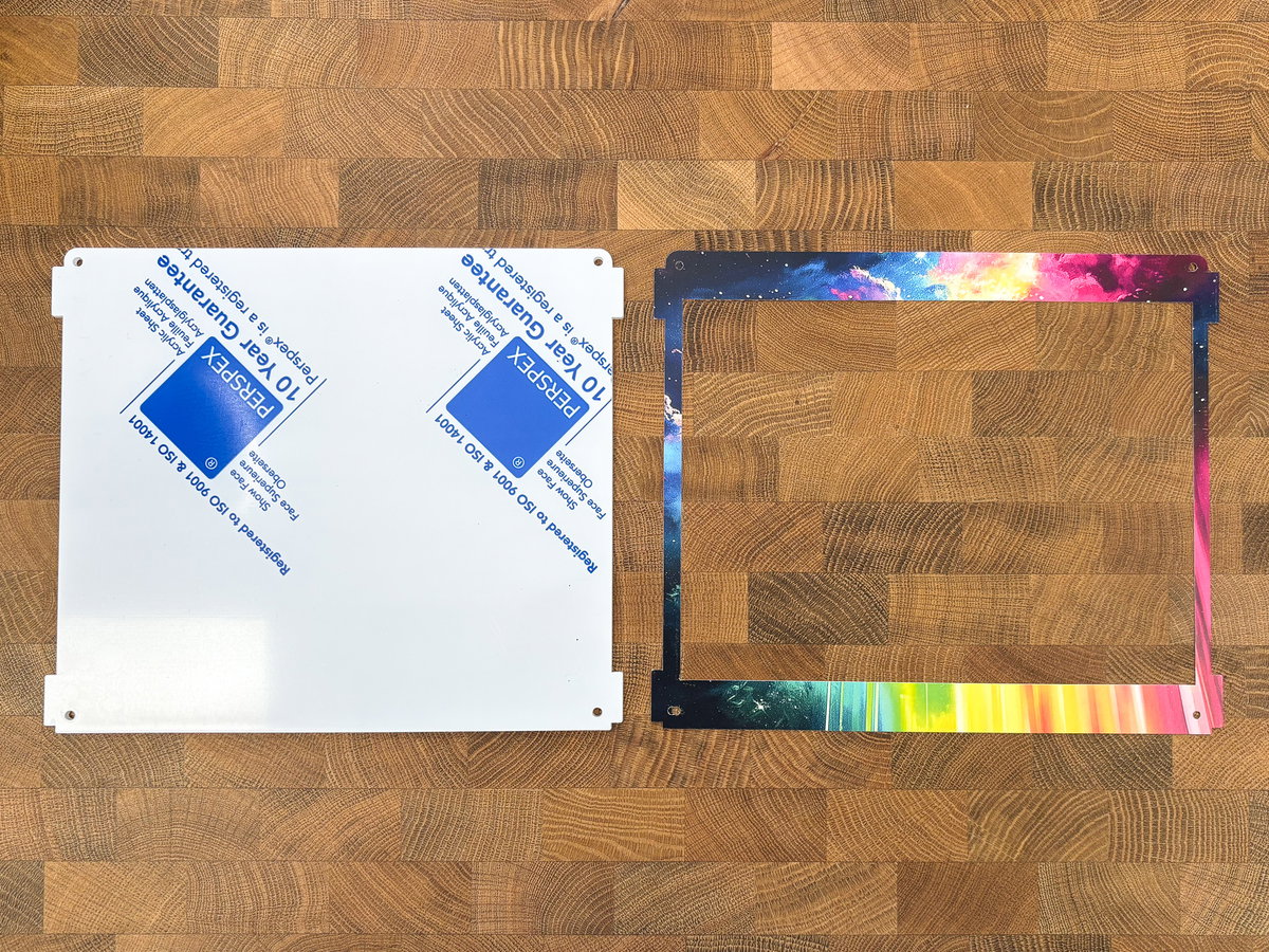
- Four curiously shaped screen mount acrylic pieces, labelled TOP and BASE
You'll also need (from the CABINET box)
- the printed cardboard screen surround
- the large square acrylic screen piece
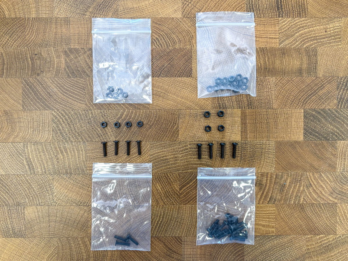
Finally, you'll need (from the bolt pack):
- 4x M3 bolts
- 4x M3 nuts
- 4x flat headed M2.5 11mm bolts
- 4x M2.5 nuts
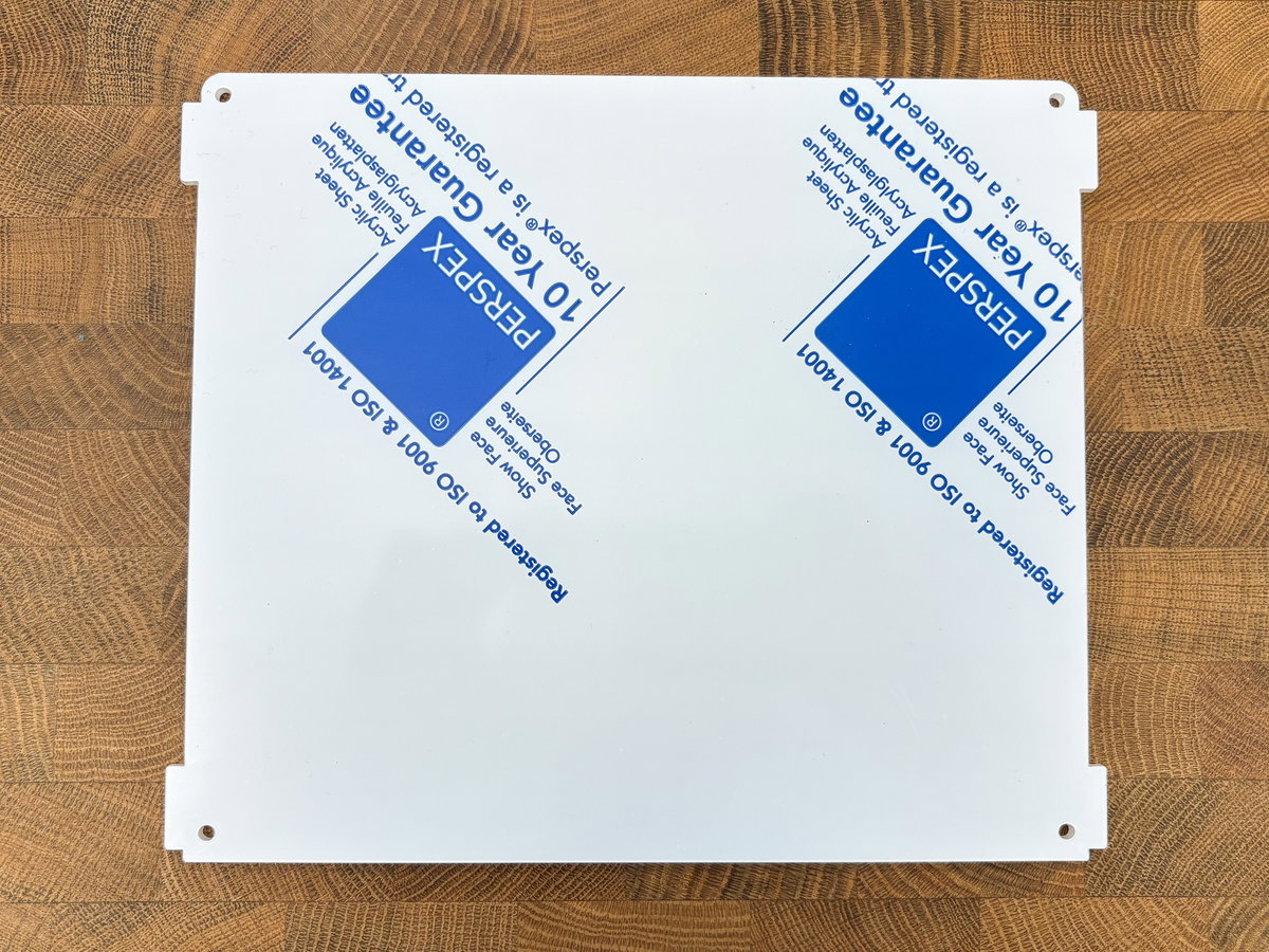
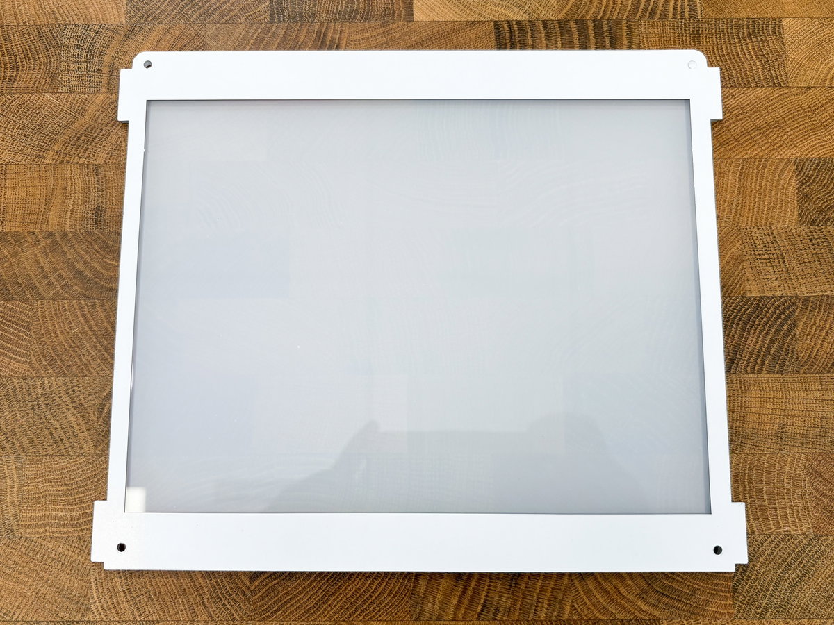
Take the large square acrylic piece and lay it down with the tabs on either side, and the curved edge at the top.
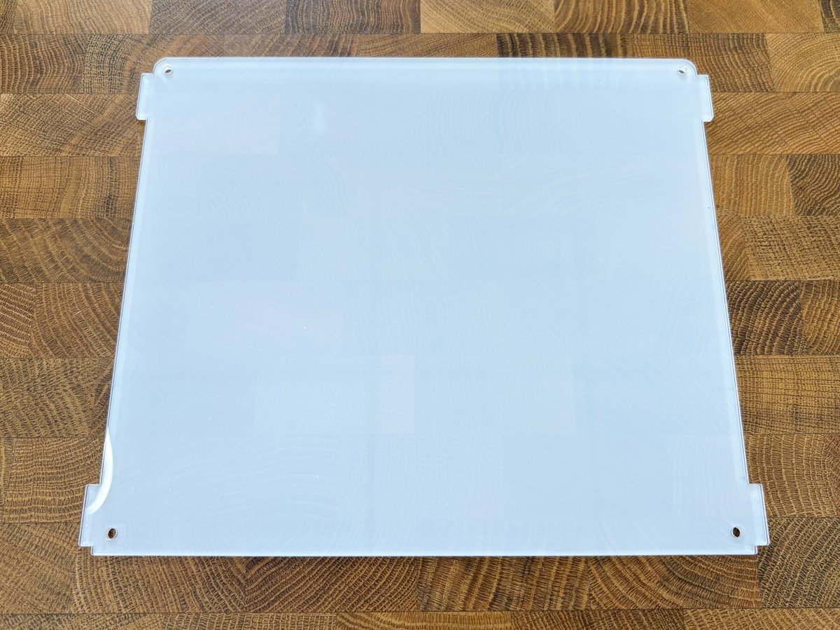
All of the acrylic pieces come with protective film on both sides. You'll need to peel this off each of the pieces as you use them, but we'll be leaving the layer on the outside of this large screen piece until the end of the build to protect it.
Peel off the protective layer on one side of the large screen piece. This will be the inside of the screen assembly so try not to get any dust, fingerprints, crumbs or pet hair on this surface, as it will be difficult to get rid of once the pieces are sandwiched together.
Place the screen surround artwork face down onto the exposed acrylic, also with the curved edge at the top.
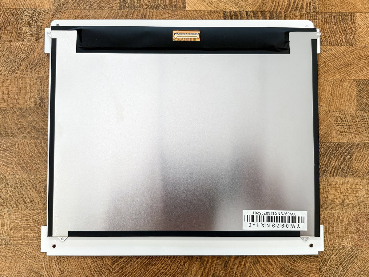
Remove the protective film from the screen itself using the tab at the side (being careful to avoid fingerprints here also), and place the screen facedown on top of the cardboard. The gold display connector should be next to the curved top edge.
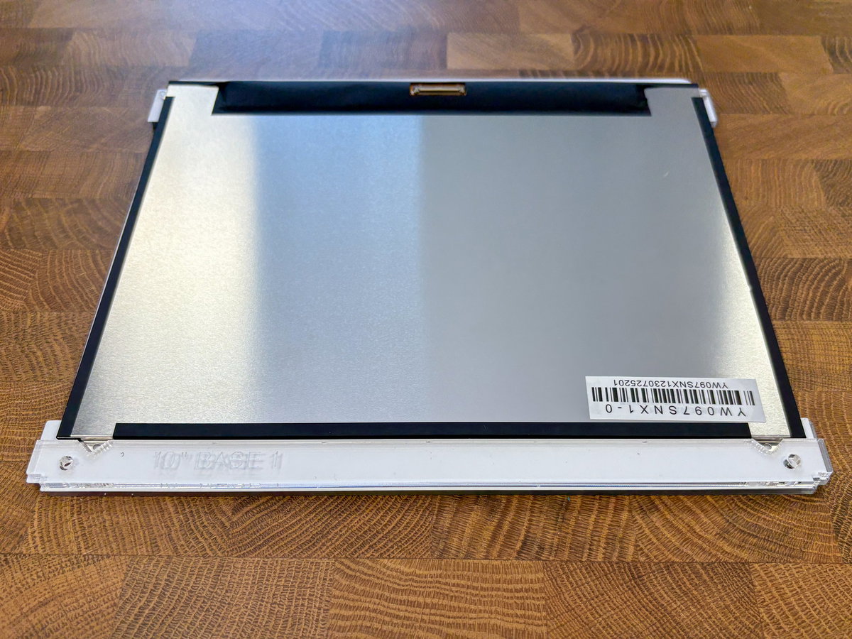
Next we'll be fitting the acrylic mounting pieces to hold the screen in place. Find the narrow, clear acrylic piece marked 10" BASE 1, remove the protective film, and place it below the screen. The 10" BASE 1 label should be right way up and readable.
Poke some M3 screws through the holes in both pieces (from the screen side).
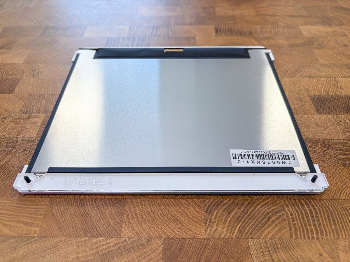
Check that the triangular notches on the bottom edge of the screen are sitting nicely into the notches on the acrylic.
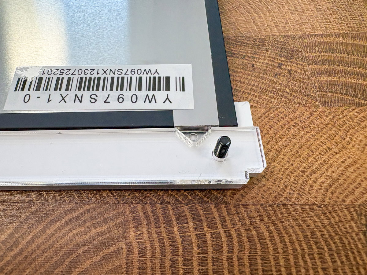
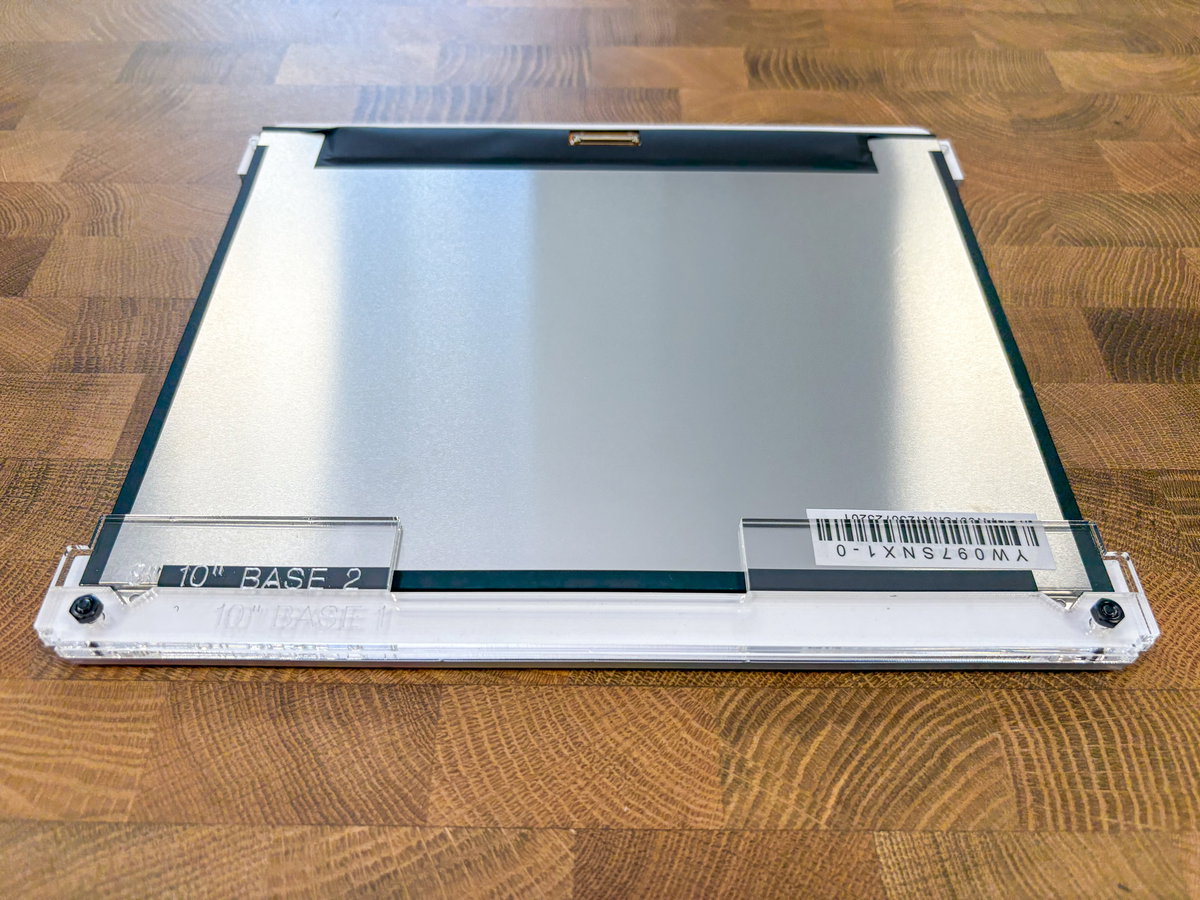
Next, slot 10" BASE 2 onto the screws, again making sure the label is the right way up and readable. Fix everything in place with a couple of M3 nuts. Note that as we're using metal fixings on acrylic here, you should take care not to tighten them up too much and crack the acrylic. Finger tight is fine.
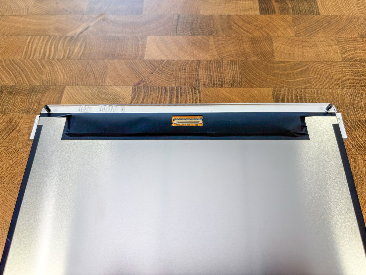
Next, poke two M3 screws through the holes in the top edge and add 10" TOP 1 to the top edge of the screen assembly. The curve in the acrylic should match the curve at the top of the screen piece.
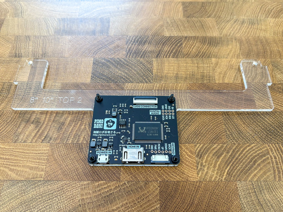
Before adding the final parts of the screen assembly, attach the display driver board to its acrylic bracket. Take the acrylic piece marked 10" TOP 2, and place it with the protruding part pointing downwards and the label the right way up. Place the driver board on top, with the HDMI and micro USB connectors at the bottom edge.
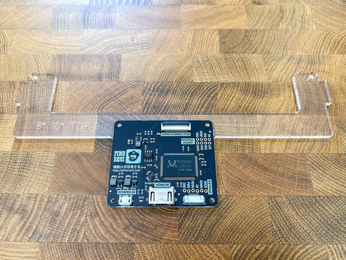
Fix the driver board in place with the M2.5 flat headed screws. The low profile screws are needed here so that this piece will sit nicely against the metal panel on the rear of screen without bending. Again, take care not to overtighten the screws and crack the acrylic.
We found it easier to connect the screen to its driver board now, before fixing the 10" TOP 2 screen mounting piece to the rest of the screen assembly. First we'll fixing the short, wide ribbon cable to the screen. This photo shows the correct orientation of the screen cable - the blue part of the cable should visible and pointing away from the screen.
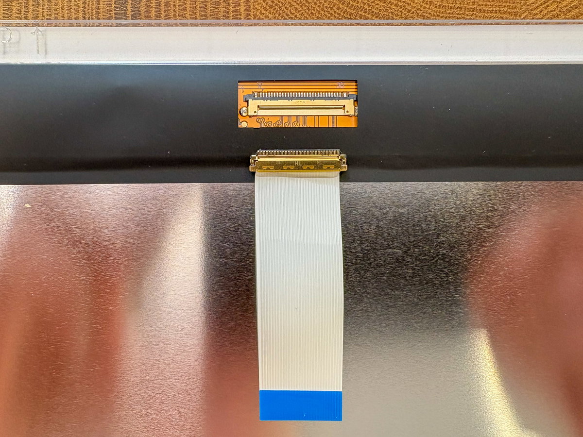
The gold end of the cable is a push-fit connector that slides into the bottom edge of the screen connector, and once you've got it correctly lined up you should be able to push in gently in using your thumbnails (don't force it). This end doesn't really lock in place, so be careful not to dislodge it when you're fitting the TOP 2 acrylic piece.
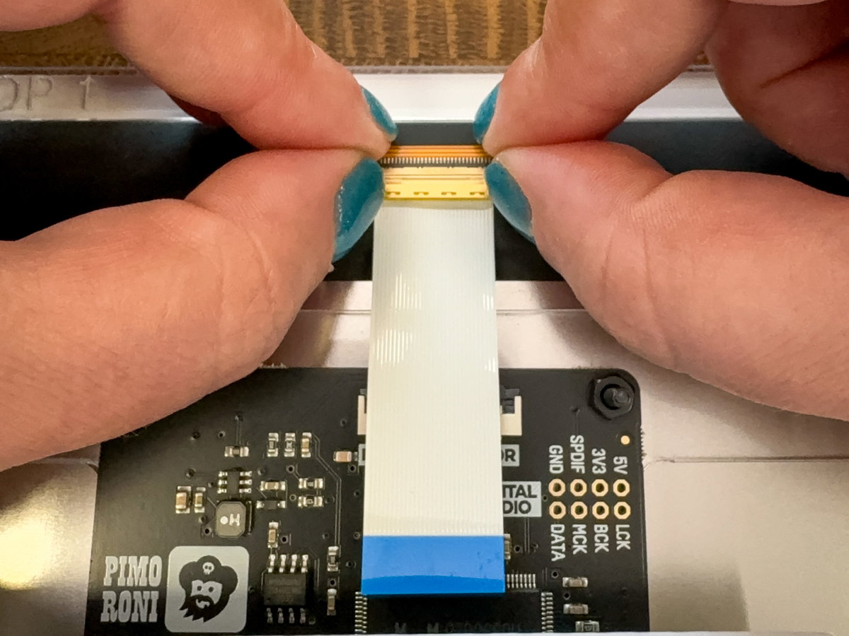
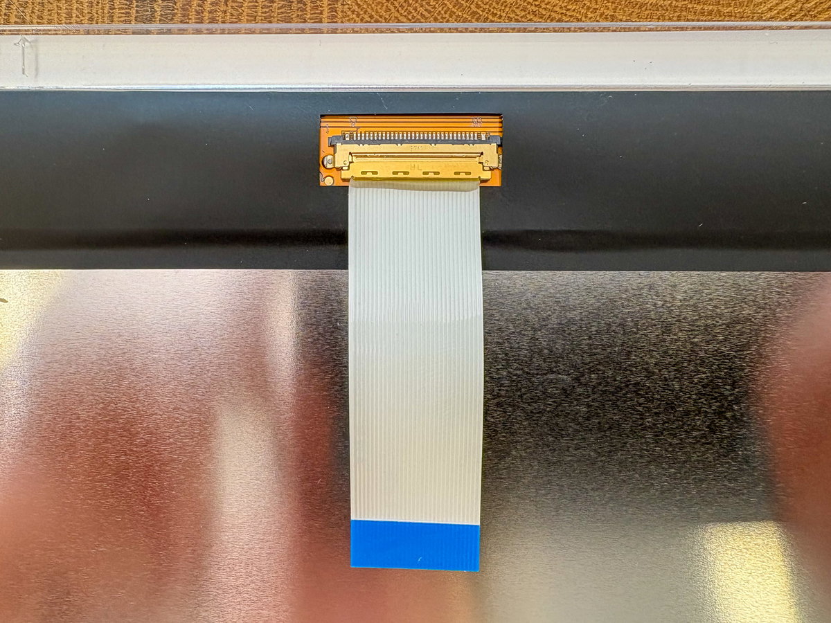
Next we'll be attaching the other end of the cable to the screen driver board. Carefully flip up the grey tab of the LVDS connector on the driver board so it's pointing towards you. You should then be able to slot the blue end of the ribbon cable (with the blue side facing up) into the open LVDS connector - make sure it goes underneath the row of little metal prongs inside the connector.
If you have trouble inserting this end of the cable into the connector, check that the grey tab is fully open - take care not to bend it back too far though, as the clips are reasonably delicate.
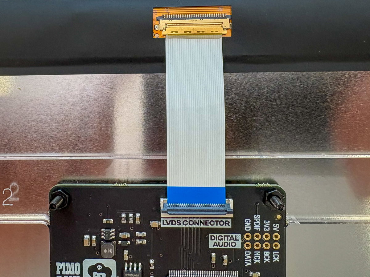
Flip the grey tab back down to secure the cable in place.
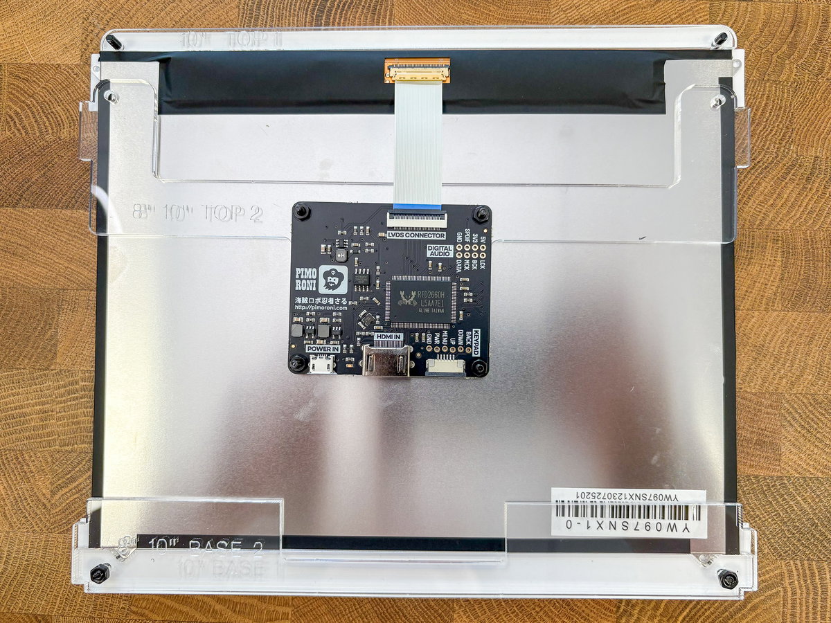
Now you can place the 10" TOP 2 bracket on top of the screen assembly. You might need to gently encourage the screen cable to flex upwards so that you can line up this acrylic piece.
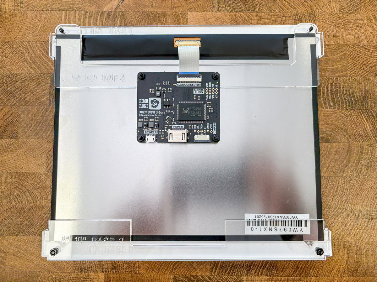
Secure everything in place with two more M3 nuts.
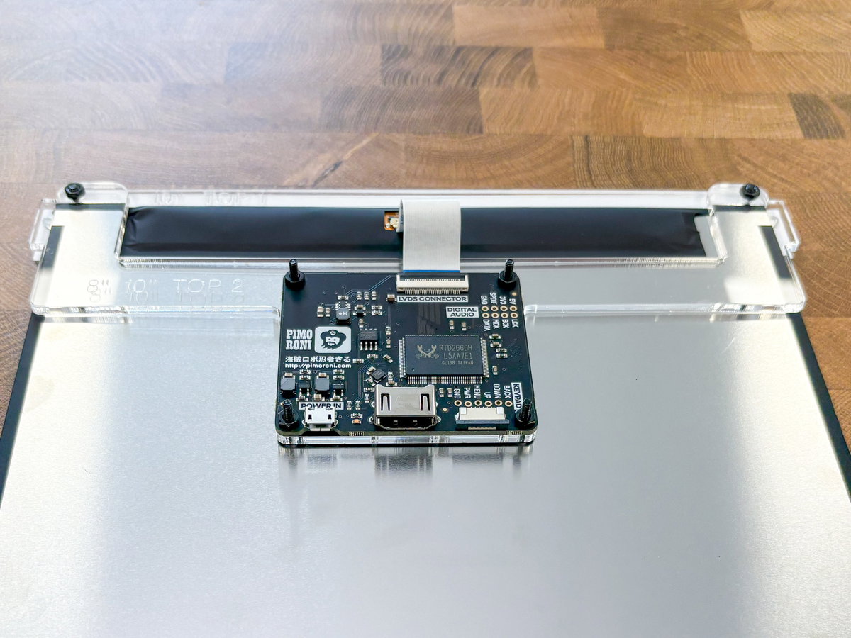
You can plug the long narrow keypad cable into the driver board now (though we won't be attaching the keypad until later). Time for another kind of connector! You can open the keypad connector on the driver board by carefully sliding the grey part away from the white part, allowing you to poke the ribbon cable into the slot in the connector. Like the last one, the blue side of the cable should be facing towards you, away from the board.
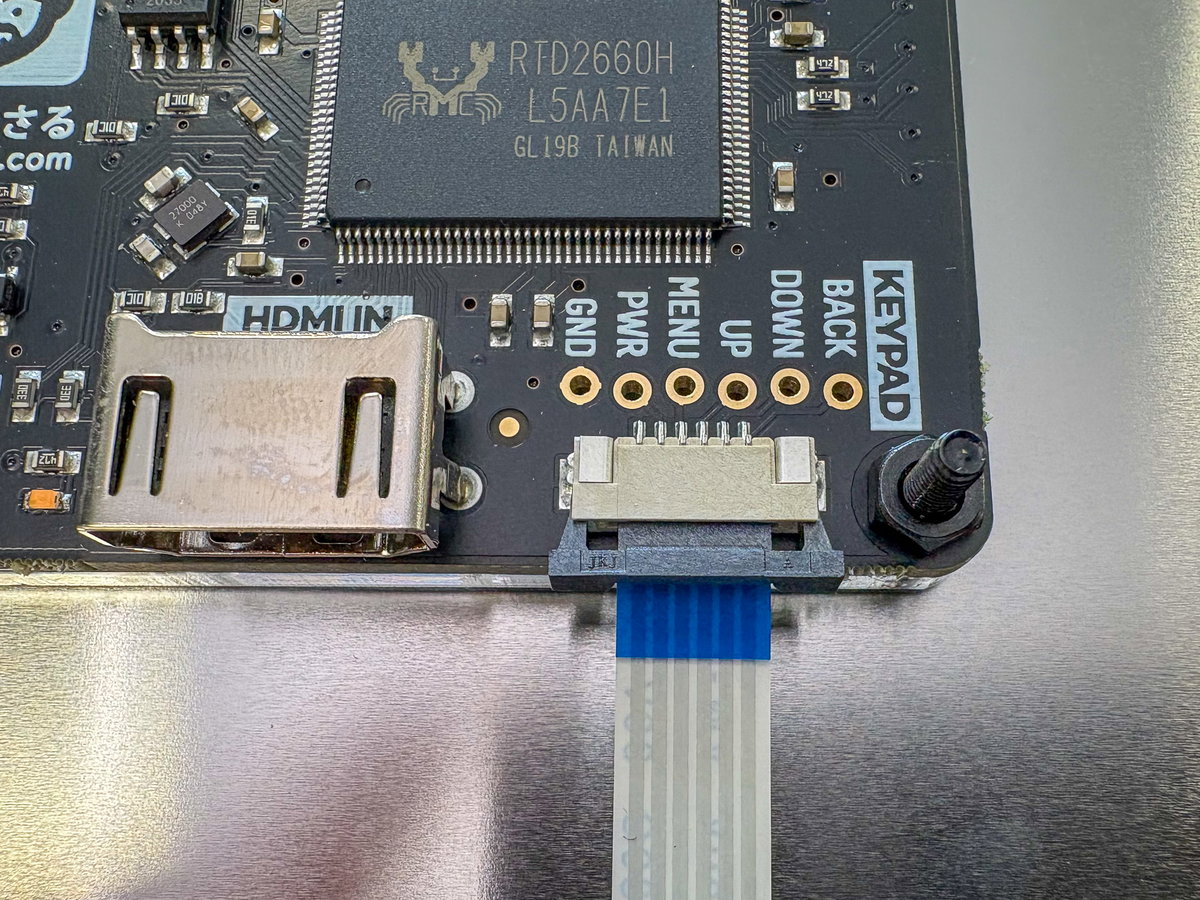
You can then slide the connector back into position - if it's plugged in correctly, the cable should be locked in place. Note that the ribbon cable for the keypad should go underneath the grey plastic clips on the connectors on both the keypad and display driver board. If you insert the cable on top of the grey plastic clip then you might still get it to fit but it won't work!
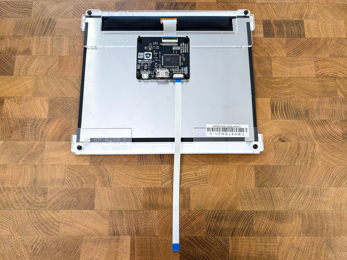
Attaching the keypad to the cabinet
We only have one item left from the SCREEN box. Might as well attach it to the cabinet now, before we lose it!
You'll need
- The screen controls keypad
- 2x flat headed M2.5 11mm bolts
- 2x M2.5 nuts
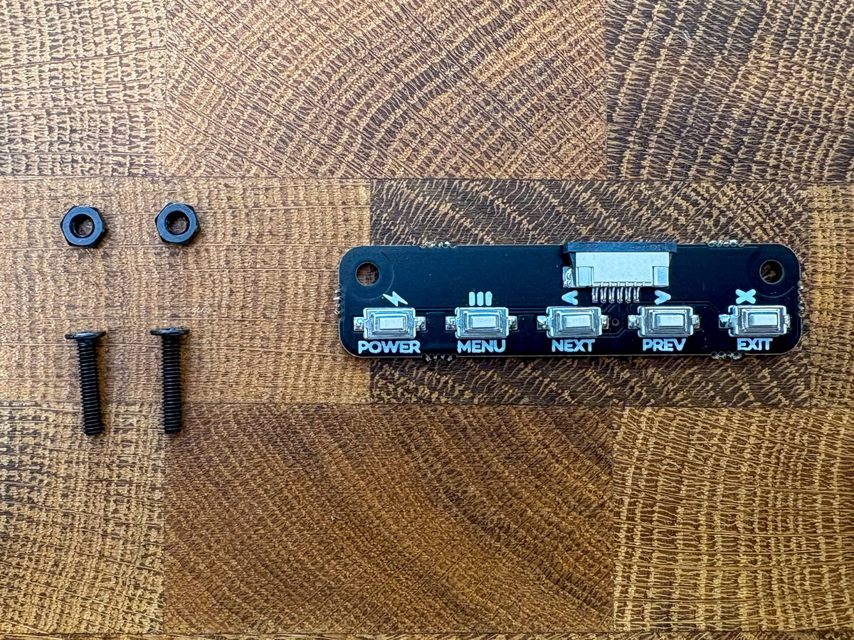
There are two holes on the left hand side near the top of panel B for attaching the keypad to the cabinet, the ribbon cable connector should point towards the front of the cabinet. Secure it in place with the M2.5 bolts and nuts, with the nuts on the inside.
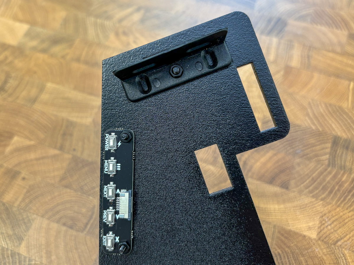
Your screen assembly is done! That's probably the fiddliest bit over with, so reward yourself with a cup of tea or something nice.
Continuing cabinet assembly
We'll now be adding the screen assembly, the marquee assembly (that's the bit that sits above the screen with the Picade logo on) and the top panel to the cabinet. You might find it helpful to turn the Picade onto one of its sides for this next bit, as you'll be wrestling a lot of things into slots at the same time and it's easier to get them lined up if they're supported at one end.
Adding the screen assembly
If you've still got the protective plastic on the front of the screen assembly, unpeel the tabs. This will make it easier to remove the rest of the plastic later on, once the tabs are in their slots.
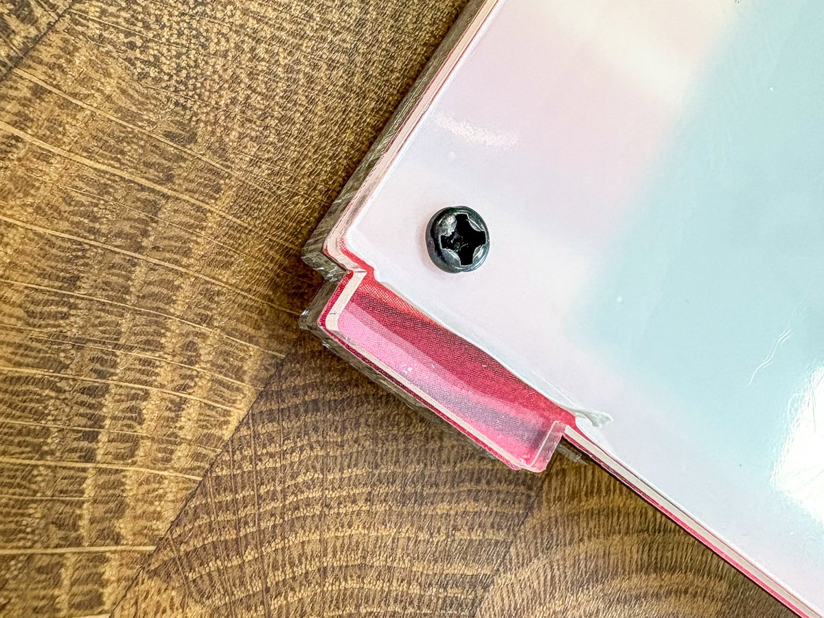
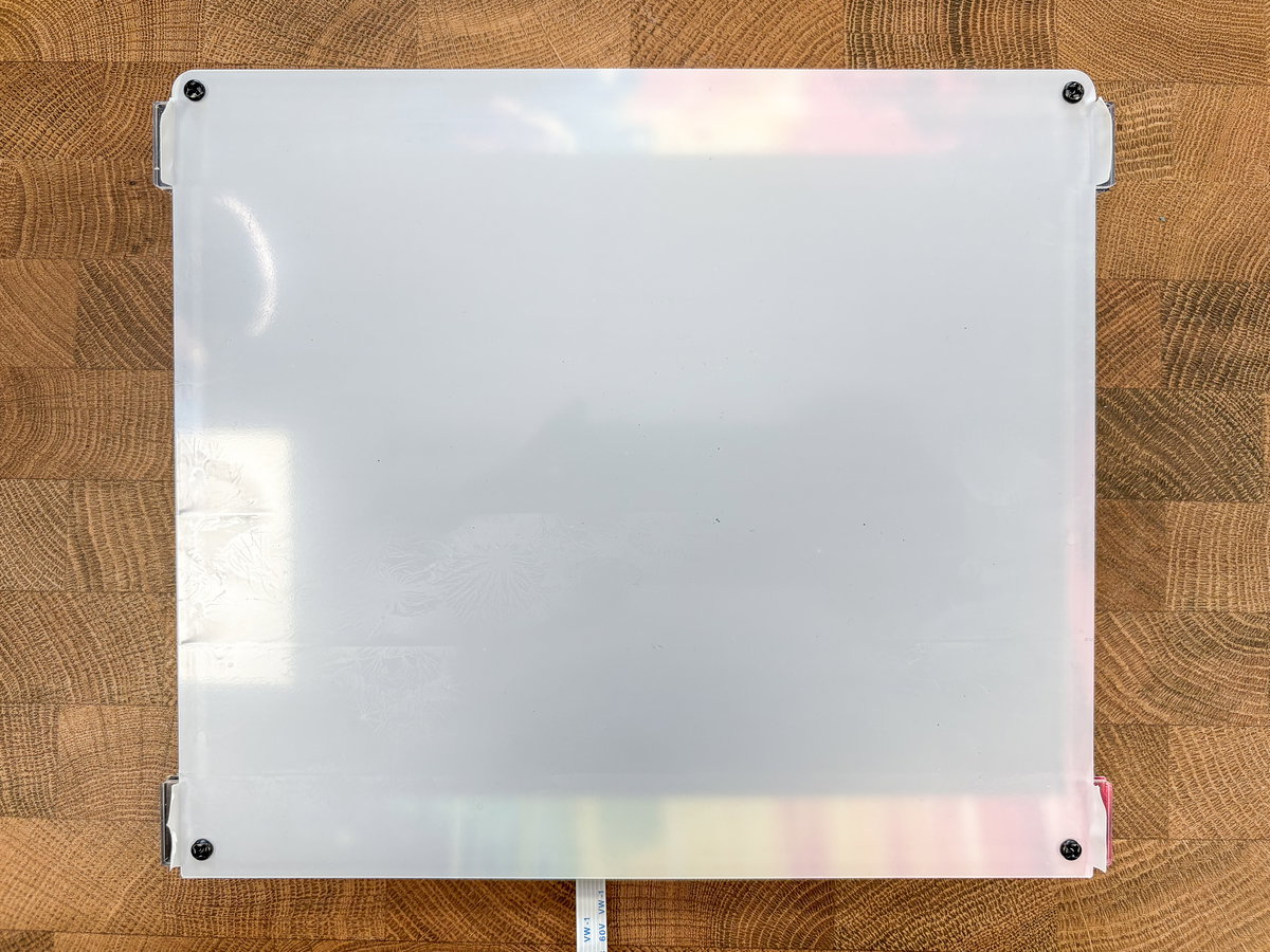
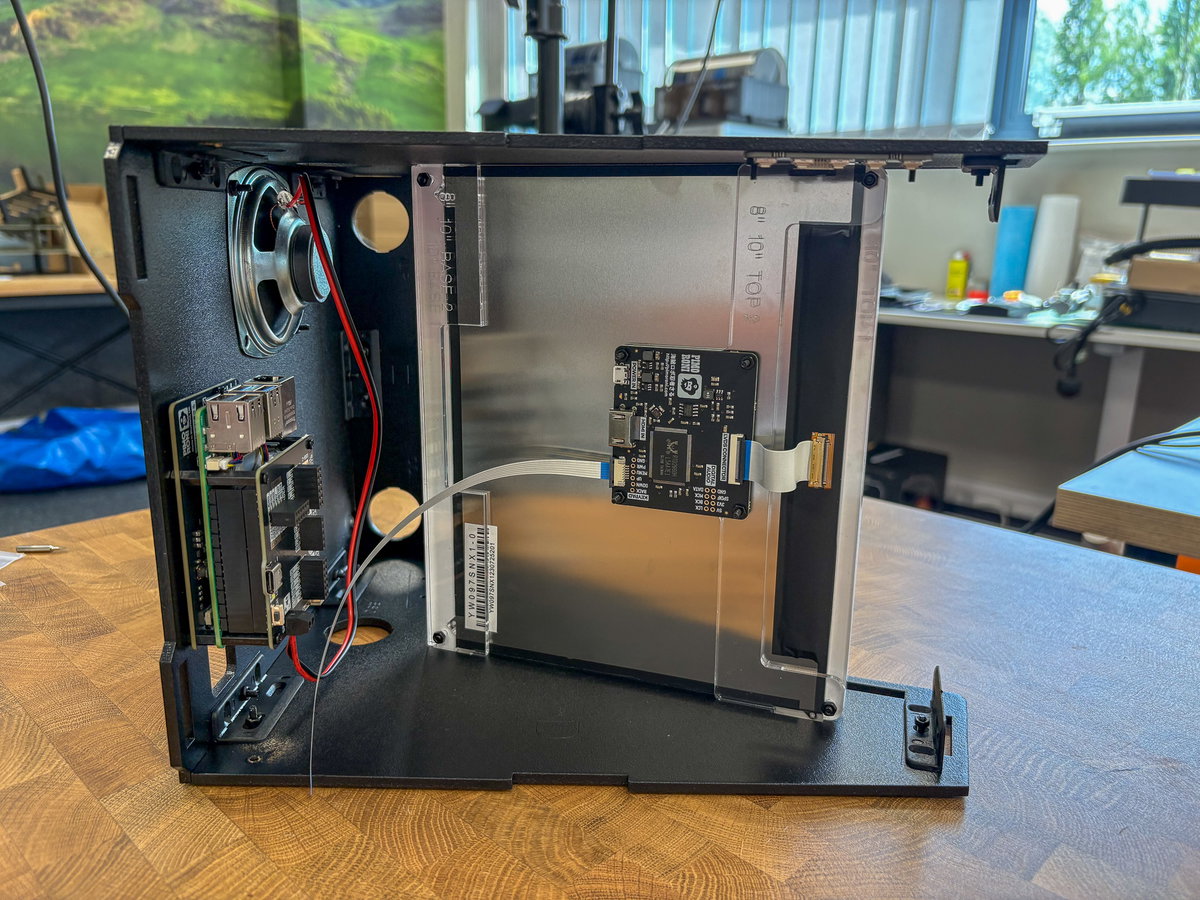
Then insert the tabs on the screen assembly into the four matching slots at the front of the cabinet, making sure the curved edge of the screen assembly is at the top of the cabinet. As we've not fitted the top yet, there should still be enough flex in the cabinet to wiggle them in.
Adding the marquee assembly and the top panel
For the next part you'll need:
- 2x transparent acrylic marquee pieces
- 1x marquee artwork
- 1x wooden panel C
- 4x M3 screws
- 4x M3 nuts
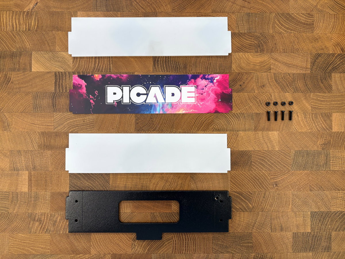
Remove the protective layer from one of the pieces of acrylic.
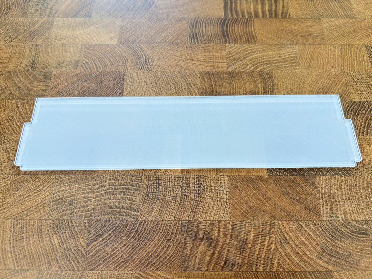
Put the artwork on top of the acrylic layer, with the printed side of the artwork touching the exposed acrylic.
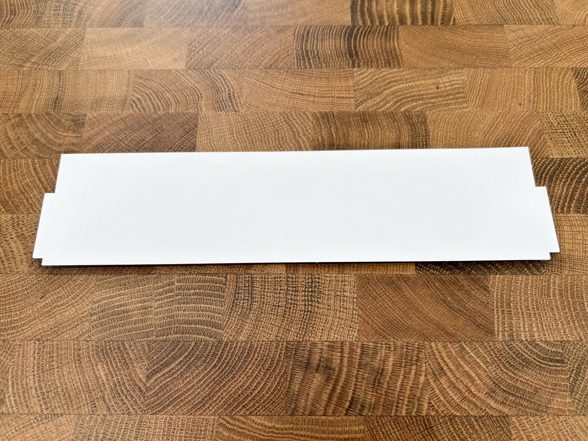
Remove the protective layer from both sides of the other piece of acrylic, and put it on top of the artwork.

If you want to leave the protective coating on the front of the marquee sandwich attached for now, unpeel it from the tabs as before
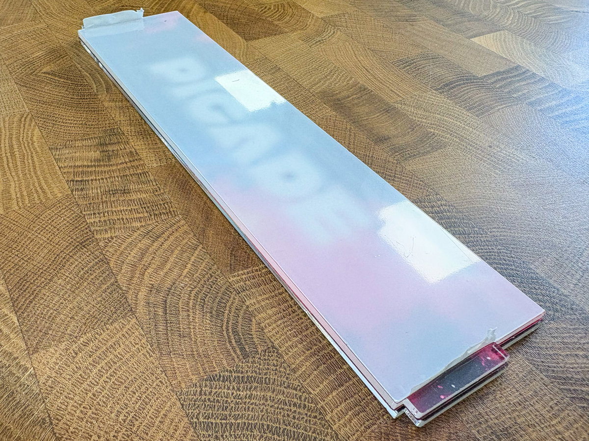
Now you can slot the marquee sandwich into the corresponding slots on the cabinet, with the art side pointing forwards. Note that the display assembly will do its best to escape from its slots at this point, so it's very helpful to have an extra pair of hands holding it in place.
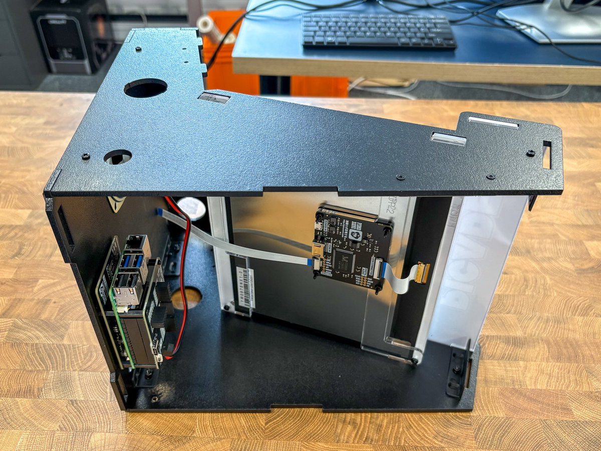
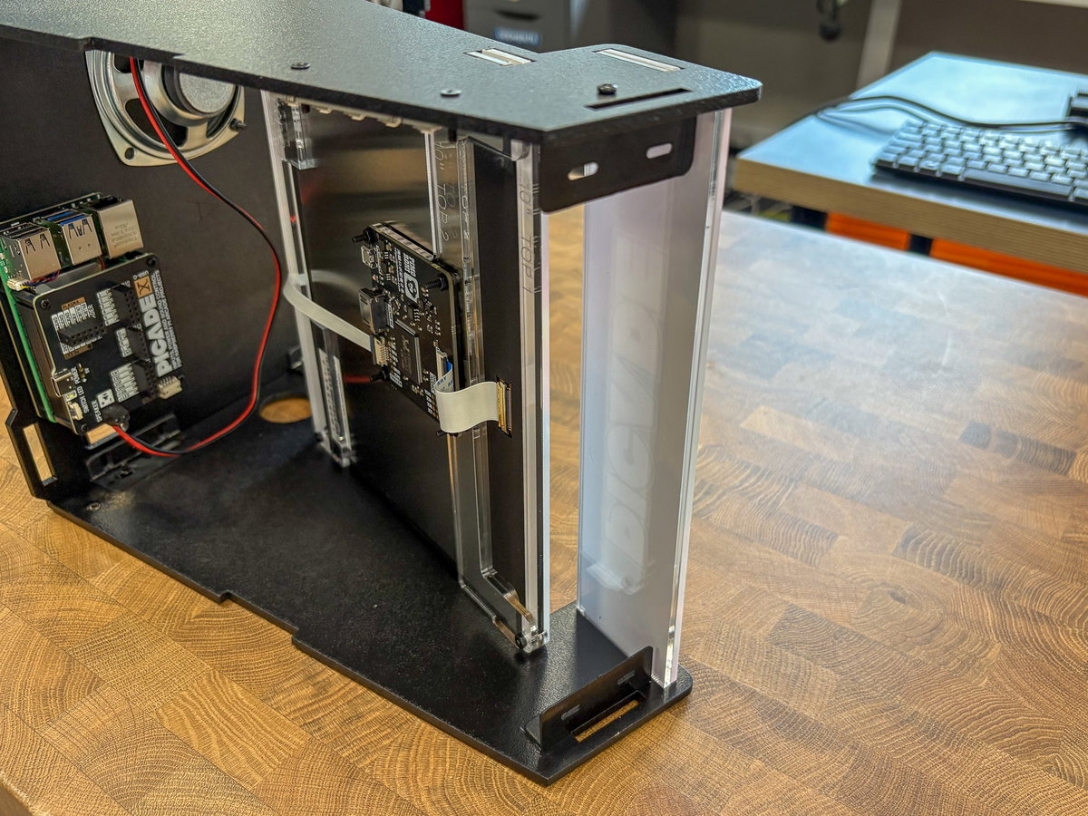
To complete the body of the cabinet, locate wooden panel C and slot it into place at the top of the cabinet. The sticky out part is the door closure so it should be pointing towards the back of the cabinet, away from the screen. As with the previous step, you might need to hold the screen assembly and the marquee assembly in place while you get everything slotted in.
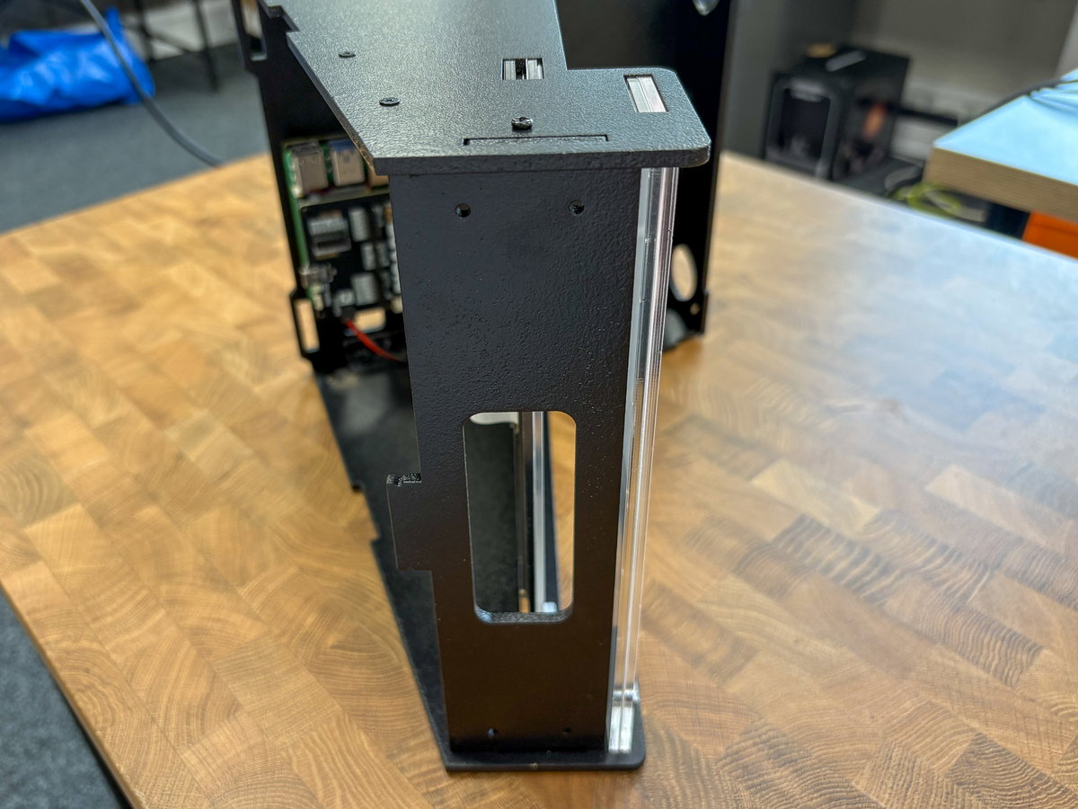
Once everything's in place, you can use four M3 nuts and bolts to attach top panel C to the brackets, which should secure everything. You can now let go of all the things you were holding on to, phew!
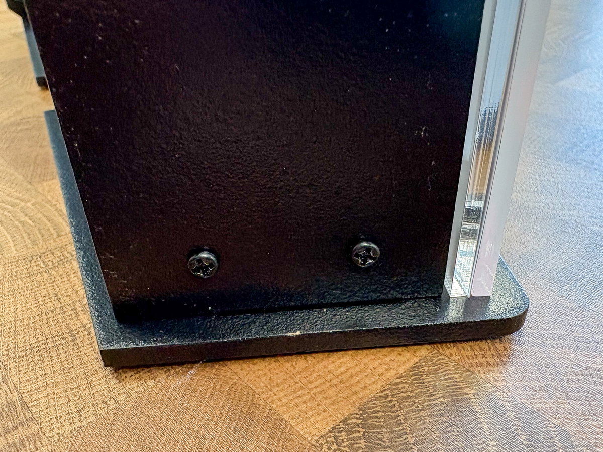
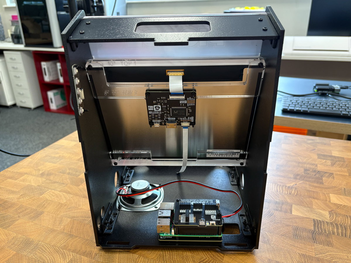
Now that the top of the cabinet is attached, it's not a bad time to go round and make sure all the screws are tightened up and the corners are square. Here's what we've made so far, from the front:
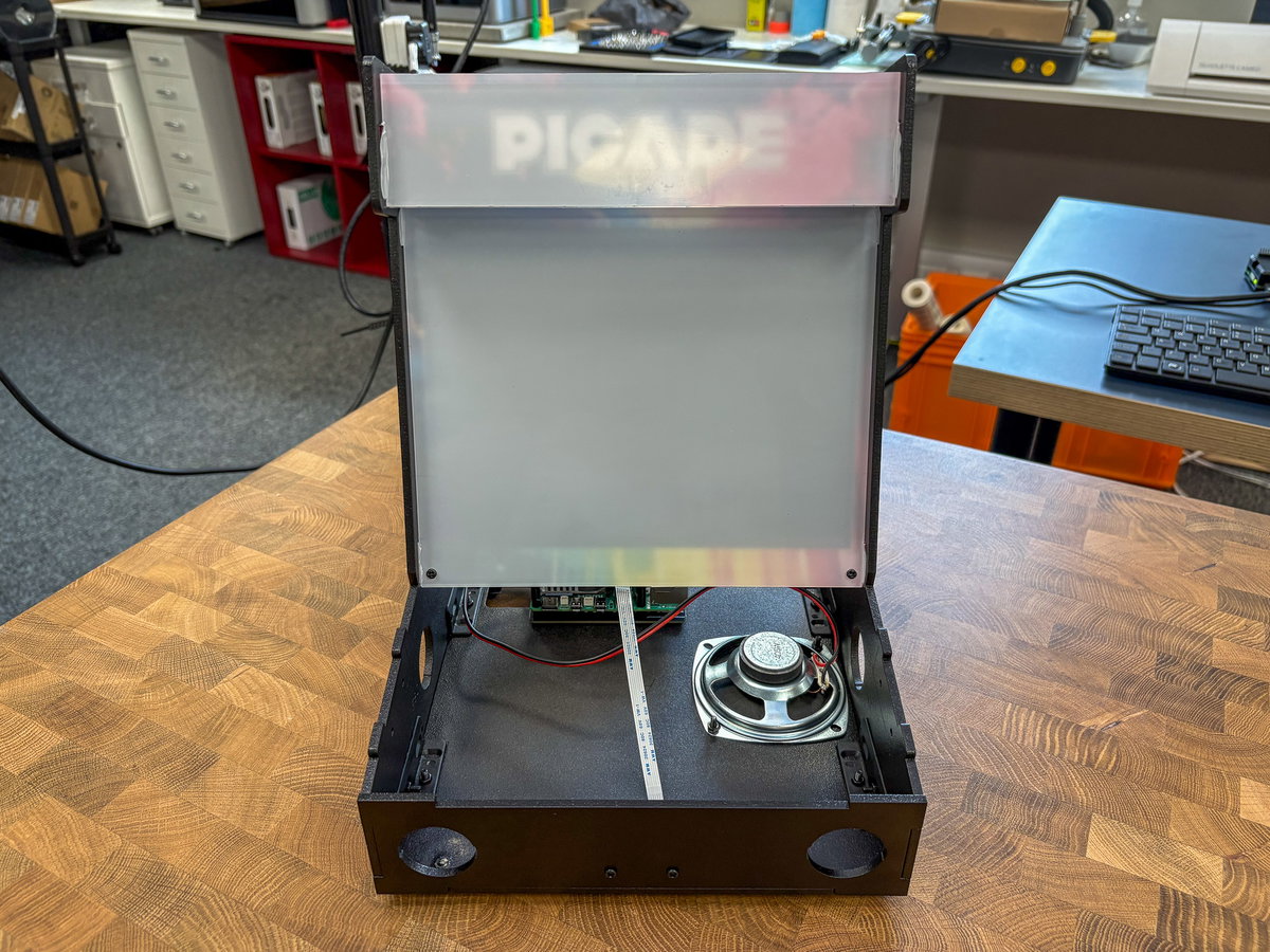
And from the back:
Plugging in the HDMI cable
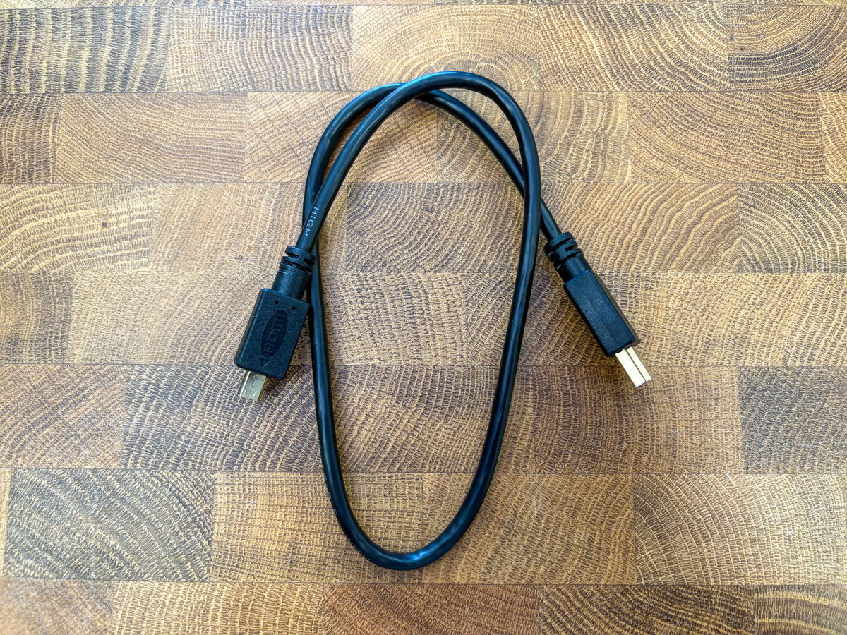
Next we'll be connecting up the cables to the screen driver board, before the wiring in the cabinet gets too busy. Locate the HDMI cable. It should be in the FIXINGS box.
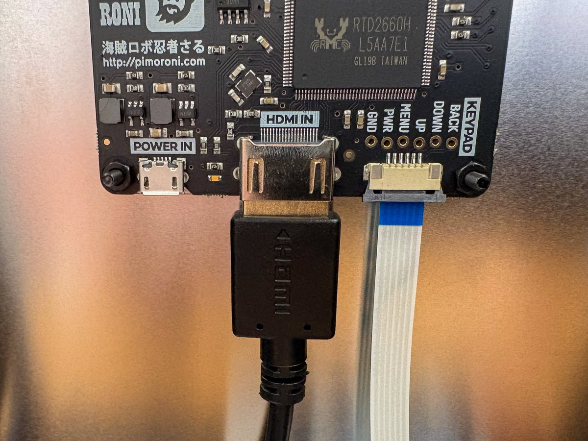
The big end goes to the HDMI IN port on the screen driver board:
And the smaller end goes to the micro-HDMI port on your Pi:
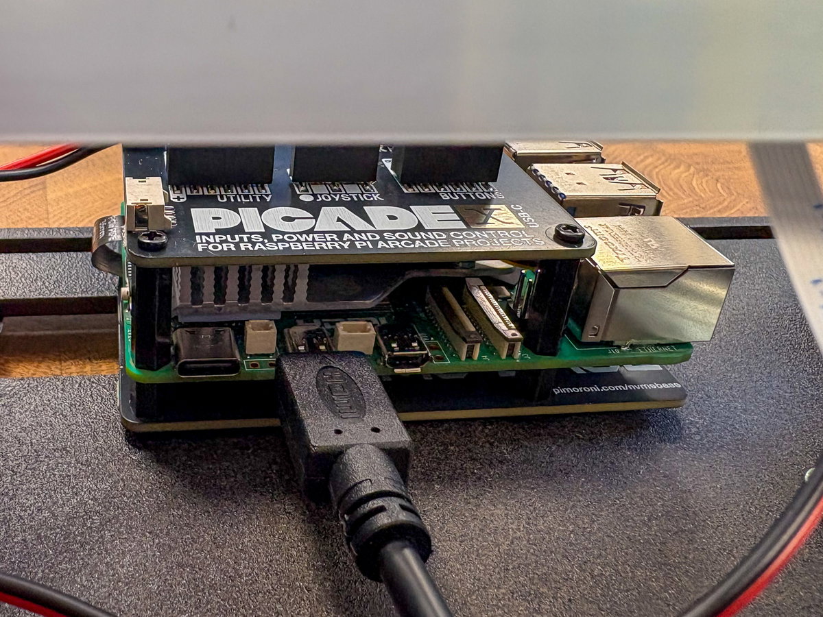
⚠ Note that recent Raspberry Pi have two micro-HDMI display ports - make sure you're plugging your cable into the default one (HDMI-0). It's the one next to the USB-C connector.
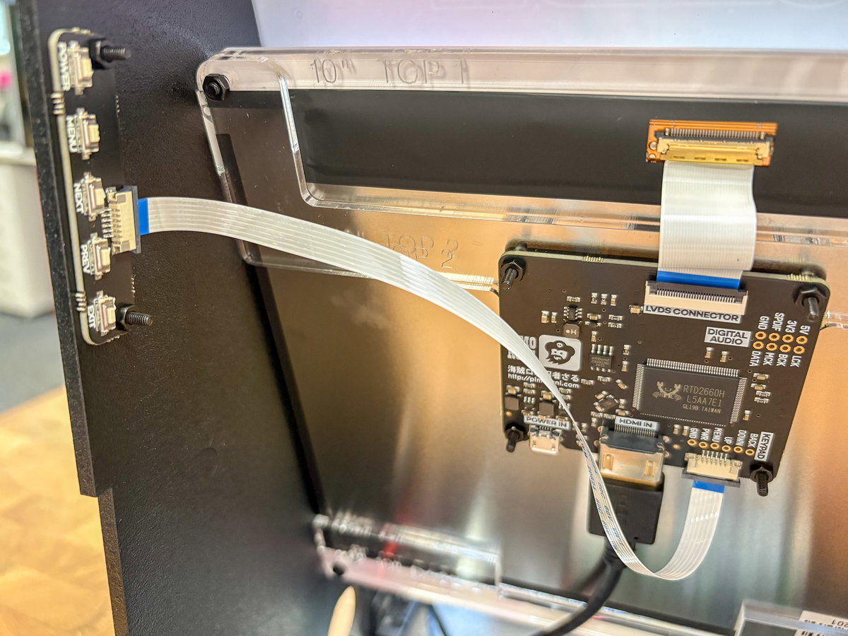
Plugging in the keypad
Attach the keypad to the loose end of the narrow ribbon cable coming from the screen driver board. The connector on the keypad is the same as the one on the other end of this cable, and you'll need to plug it in with the blue side of the cable on the same side as the keypad buttons.
Plugging in the micro-USB cable
Locate the micro-USB cable (it should also be in the FIXINGS box). This will be used to supply power to the screen.
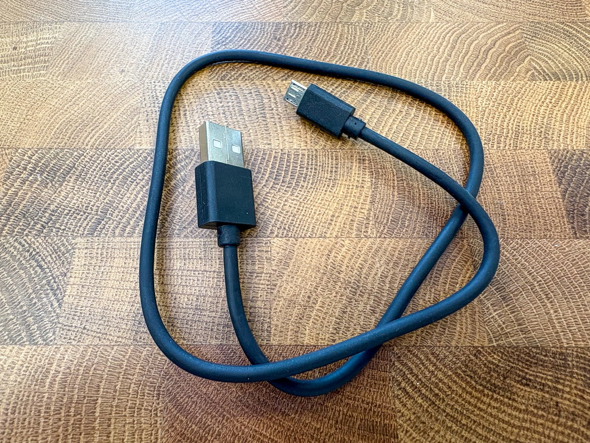
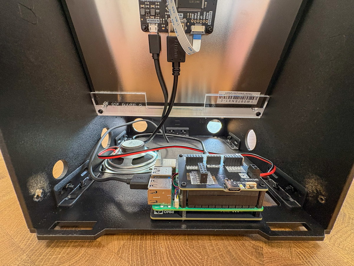
The small micro-USB end goes into POWER IN on the screen driver board, and the big USB-A end goes into one of the USB ports on the Pi.
Attaching the power button
Locate the metal power button and one of the strips of black wires from the wiring loom (they should both be in the FIXINGS box).
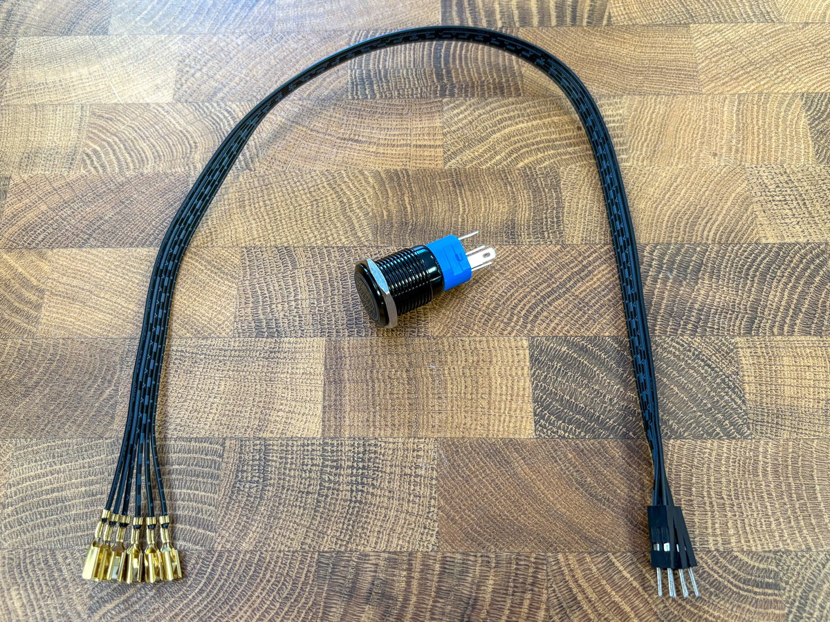
Tear off two pairs of wires from the wiring loom. One pair will be used to wire up the LED part of the button, and the other will be used to wire up the switch itself.
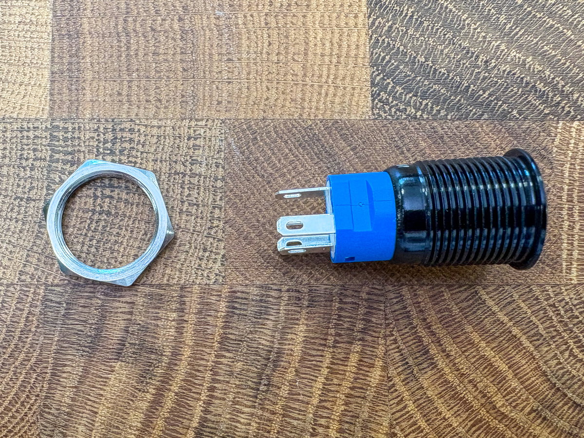
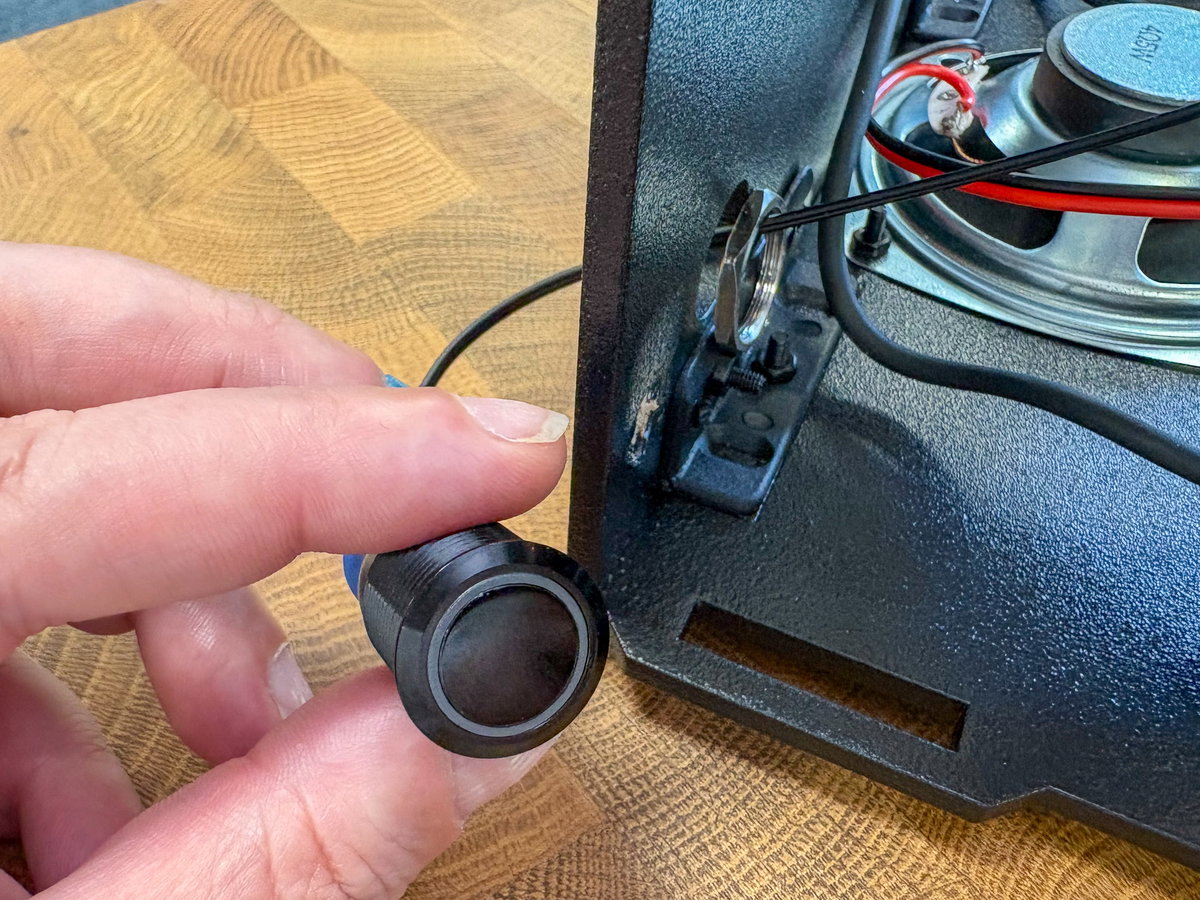
Unscrew and remove the hexagonal metal ring from the button, you'll use this to secure the cabinet to the cabinet once you've wired it up.
There are five contacts on the bottom of this button, labelled 1, 2, C, NO and NC.
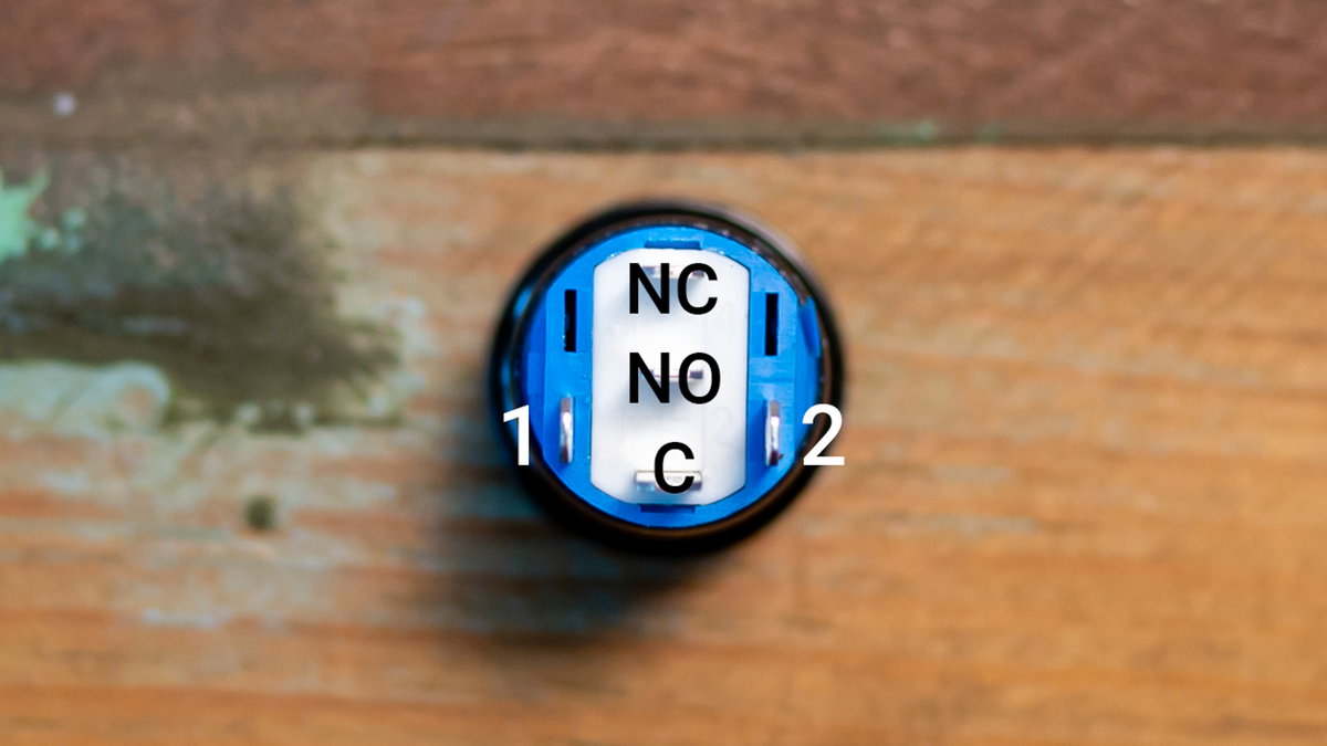
First we'll connect up the LED part of the button. Push the spade connectors on one pair of wires onto contacts 1 and 2 (the ones sticking out of the blue bit), either way round.
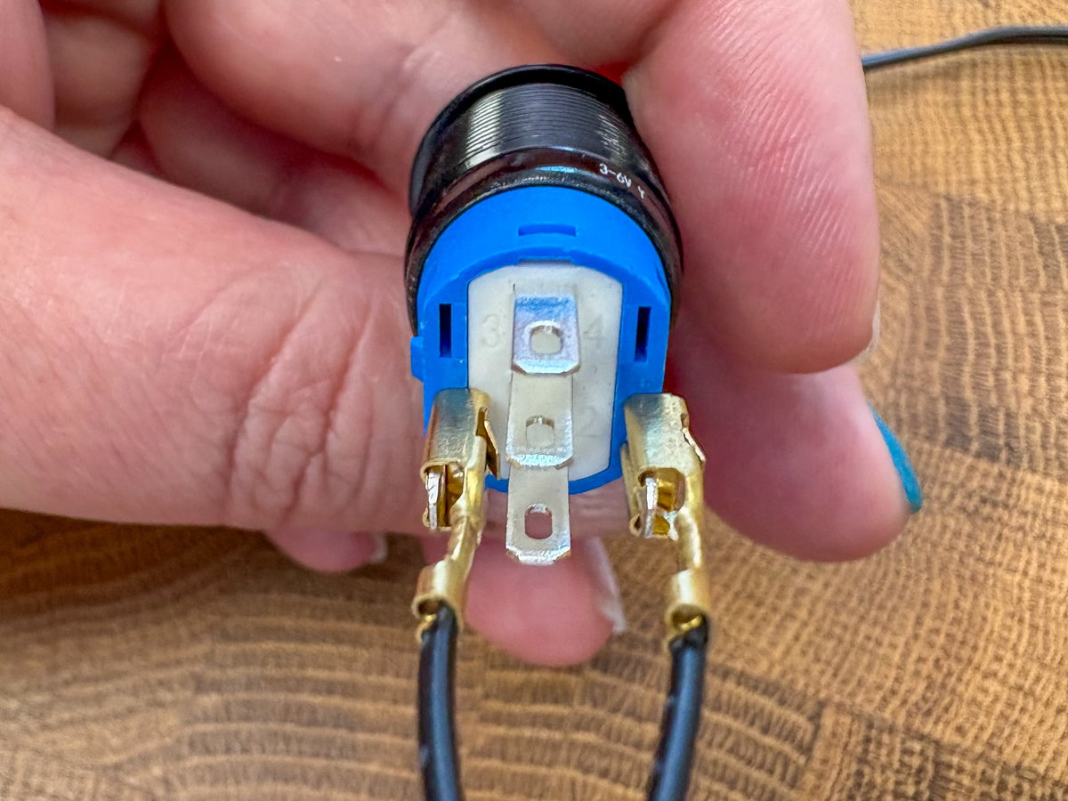
Grab the other end of the wires with the pins on and thread them through the smaller round hole in wooden panel B, and then through the hexagonal metal ring.
Plug the pin connector into the terminal connector marked LED on the Picade X HAT.
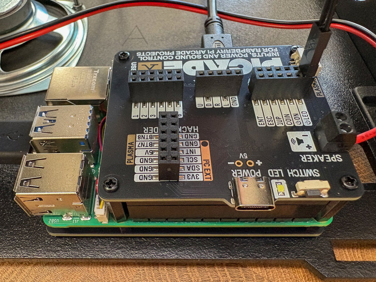
Now we need to wire up the switch part of the power button. Grab the other pair of wires and attach the spade connectors to the contacts marked C and NO on the button (they're the two contacts between the wires that you just plugged in). Double check that none of the metal connectors plugged into the back of the button are touching each other, you can gently bend the contacts slightly to separate them if they are.
Thread the other end of the wire through the hole in the cabinet and through the hexagonal ring as before. The pin connectors on this wire plug into the terminal connector marked ON.
Once everything's connected up, push the button into the hole in the cabinet and tighten up the metal ring to hold it in place.
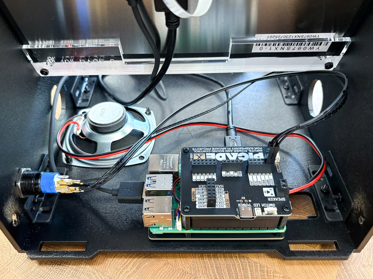
Your Picade is now two thirds complete, so now is another good time for a break, before we get started on the final stretch!
Building the console assembly
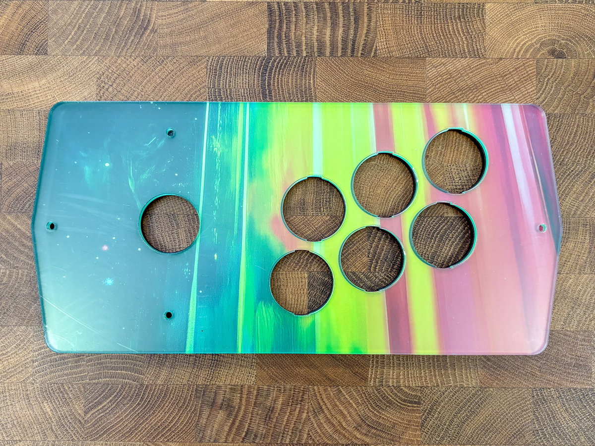
The last bit to assemble is the console assembly, where the buttons and joystick live.
For this part, you'll need:
- 1x wooden console panel
- 1x console artwork
- 1x transparent acrylic console piece
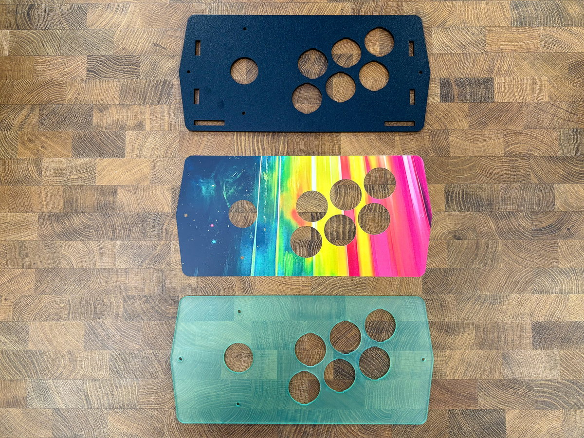
Line the three pieces up so the button holes match and the printed cardboard is facing the acrylic. Remove the protective film on the side of the acrylic that's touching the front of the artwork - you can leave the outer protective layer on until the end of the build if you wish.
Wiring the joystick
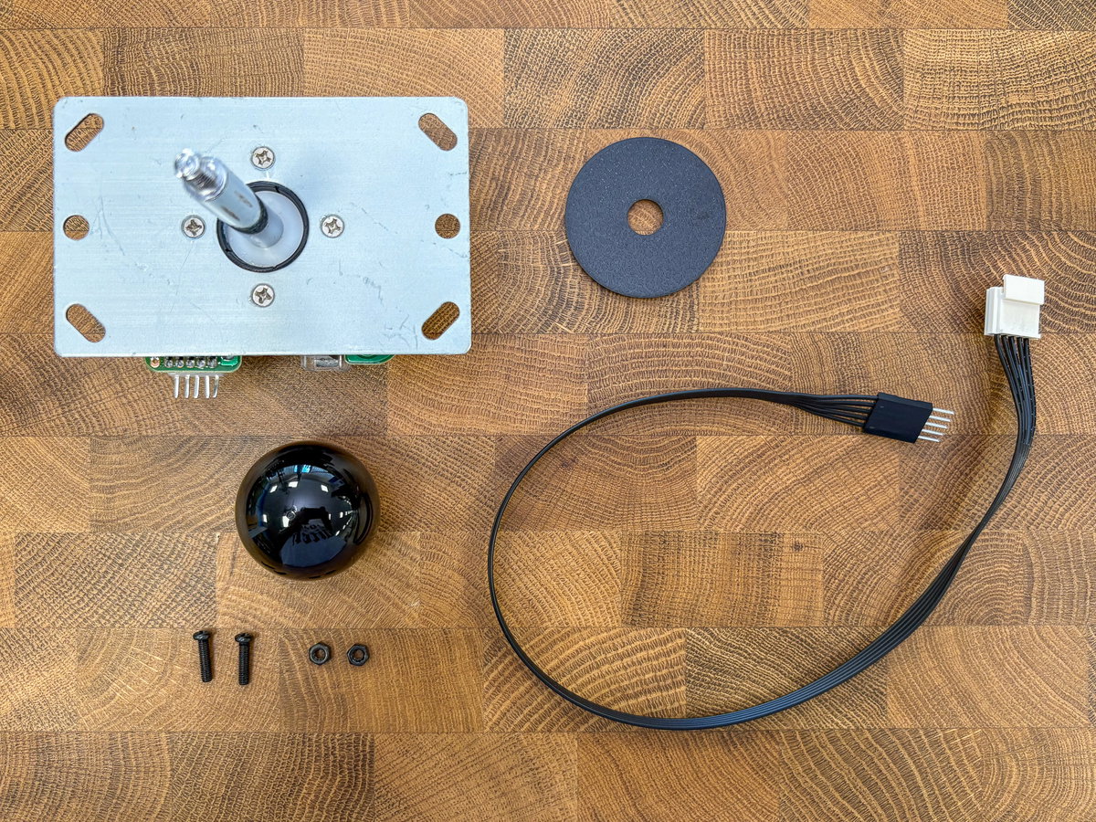
To wire up the joystick, we'll need:
- Joystick
- Joystick collar
- Joystick ball
- Joystick cable (it has five wires and a white plastic clip on the end)
- 2x M3 screws
- 2x M3 nuts
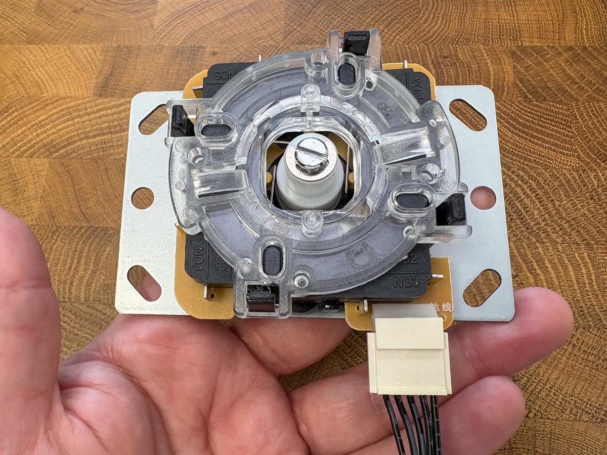
First we'll be connecting the cable to the joystick. Flip the joystick over and locate the 5 pins sticking out of one side. They sometimes get a bit bent in transit, but you should be able to straighten them out with your fingers.
The white plastic clip pushes onto the five pins on the joystick, with the locking clip and the moulded numbers on the connector facing you. This end of the cable should only fit one way round.
From the acrylic side, poke some M3 screws through the two holes surrounding the single hole in the console assembly.
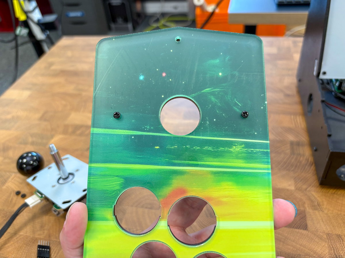
Then poke the joystick through the hole from the other (wooden) side. Orient it so the cable is pointing towards the inside of the panel.
Fasten the joystick in place with M3 nuts. Take care not to over-tighten these screws and crack the acrylic.
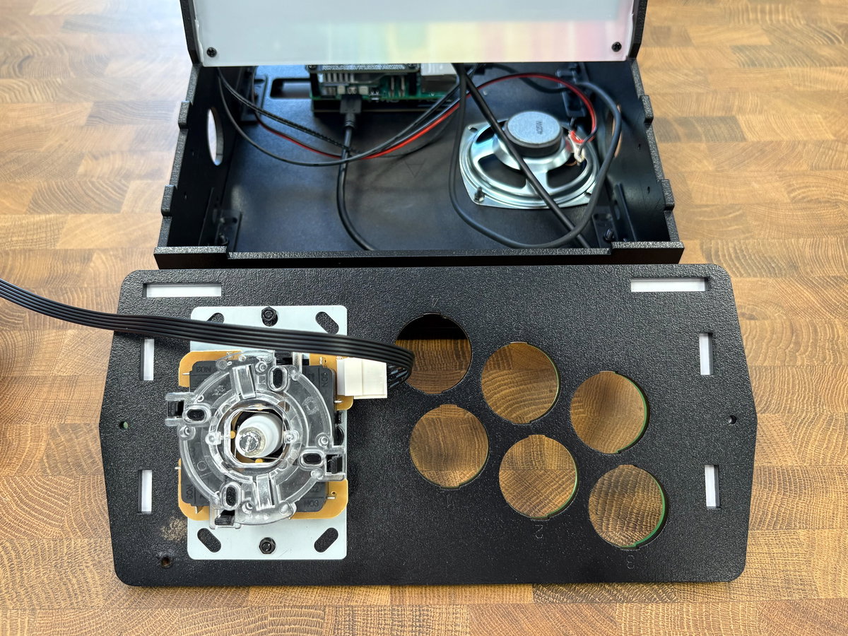
Thread the end of the joystick cable with the pins through the front of the cabinet.
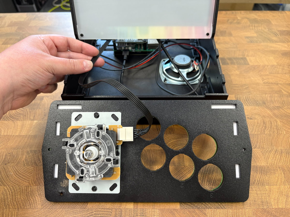
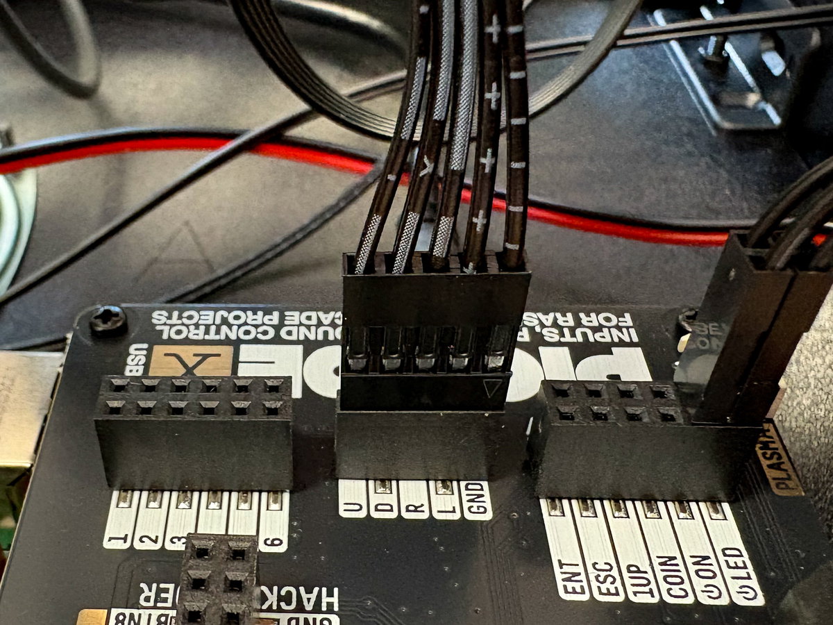
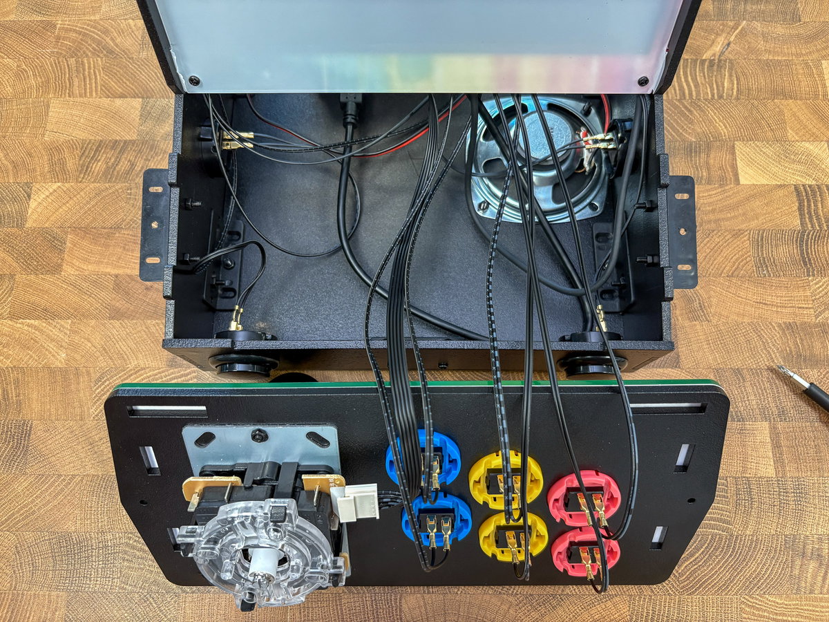
Before plugging in the joystick cable to the Picade X HAT, take a peek at the underside of the console assembly again. The GND wire is marked 1 on the white joystick connector. Follow this wire to the other end (the wires all have different markings, so this should be straightforward) and plug the pins into the JOYSTICK header on Picade X HAT, making sure that the GND wire goes to the appropriately marked header.
⚠ If your joystick only has one direction that works later when it comes to mapping the controls, then the wires have been connected back-to-front. Simply remove the pin connectors from the JOYSTICK header on the Picade X HAT, flip them 180 degrees, and plug them in again.
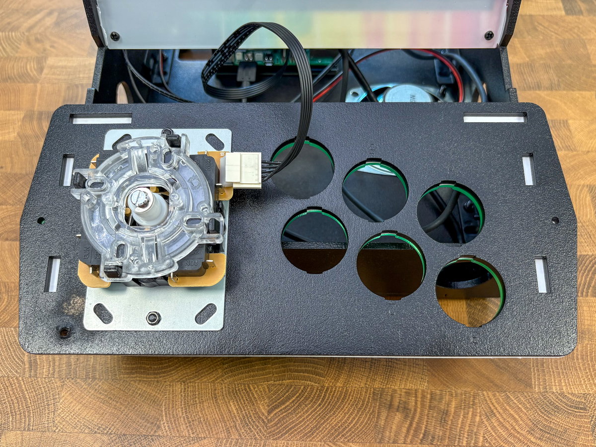
We found it helpful to balance the upside-down console assembly on the front part of the cabinet whilst we did the rest of the wiring.
Flip the console panel over temporarily so you can access the top side, and pop the dust cover collar over the joystick, and attach the ball on top. You can use a flat-head screwdriver to hold the shaft of the joystick from below while you tighten up the ball, if necessary.
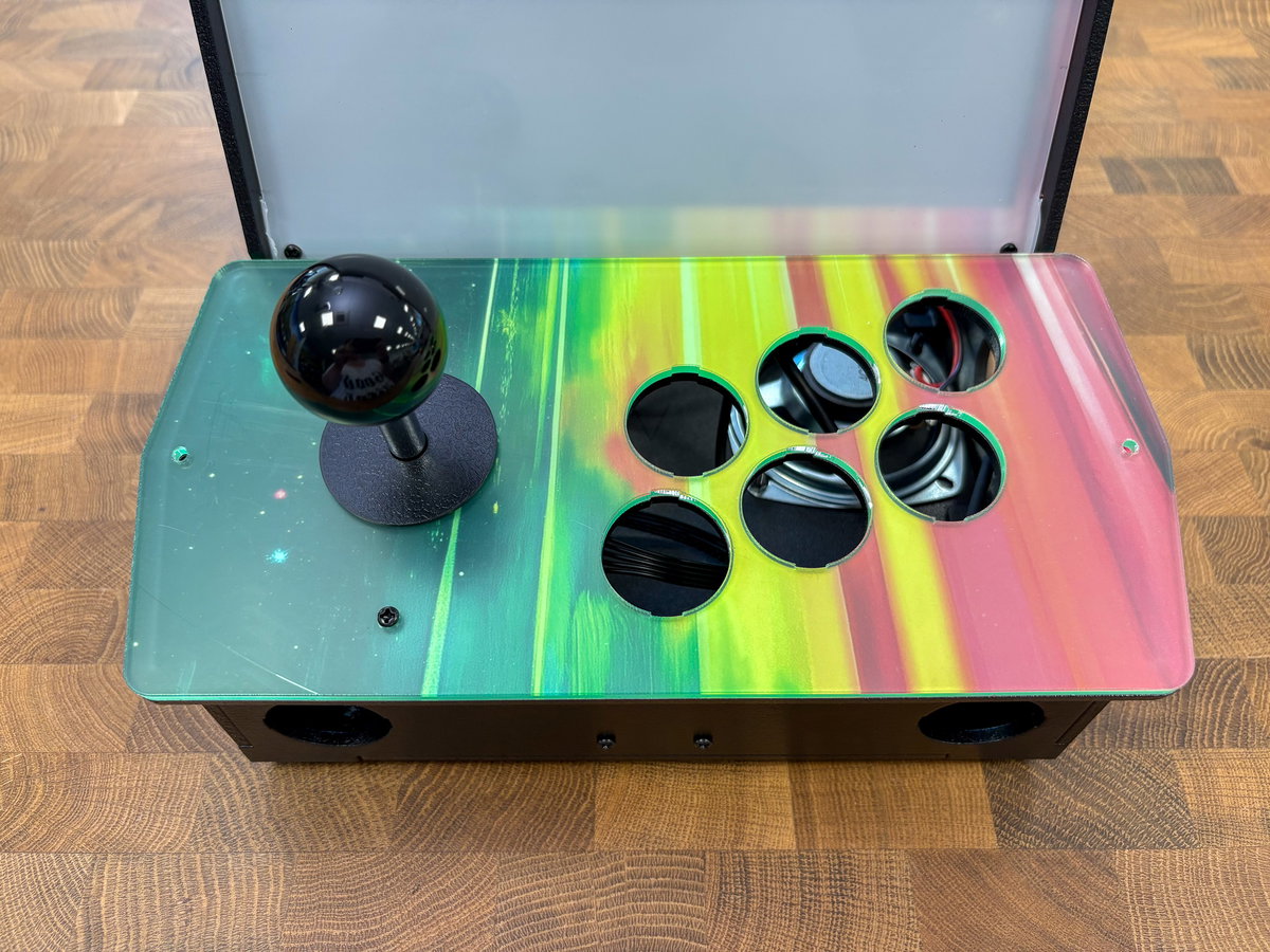
Wiring the console buttons
For the next part, you'll need:
- 2x pink arcade buttons
- 2x yellow arcade buttons
- 2x blue arcade buttons
- 2x strips of wires from the wiring loom
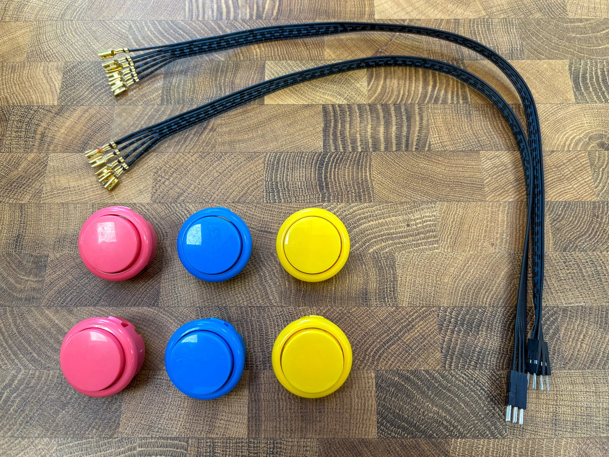
The arcade buttons are shipped to us in big bags, so the top surface can sometimes get a little scuffed up in transit. If you have some T-Cut to hand, that does a pretty nice job of shining them up again (other lightly abrasive scratch removing compounds are available).
Separate the wires into six pairs, one pair for each button. Take one pair and push the spades onto the button.
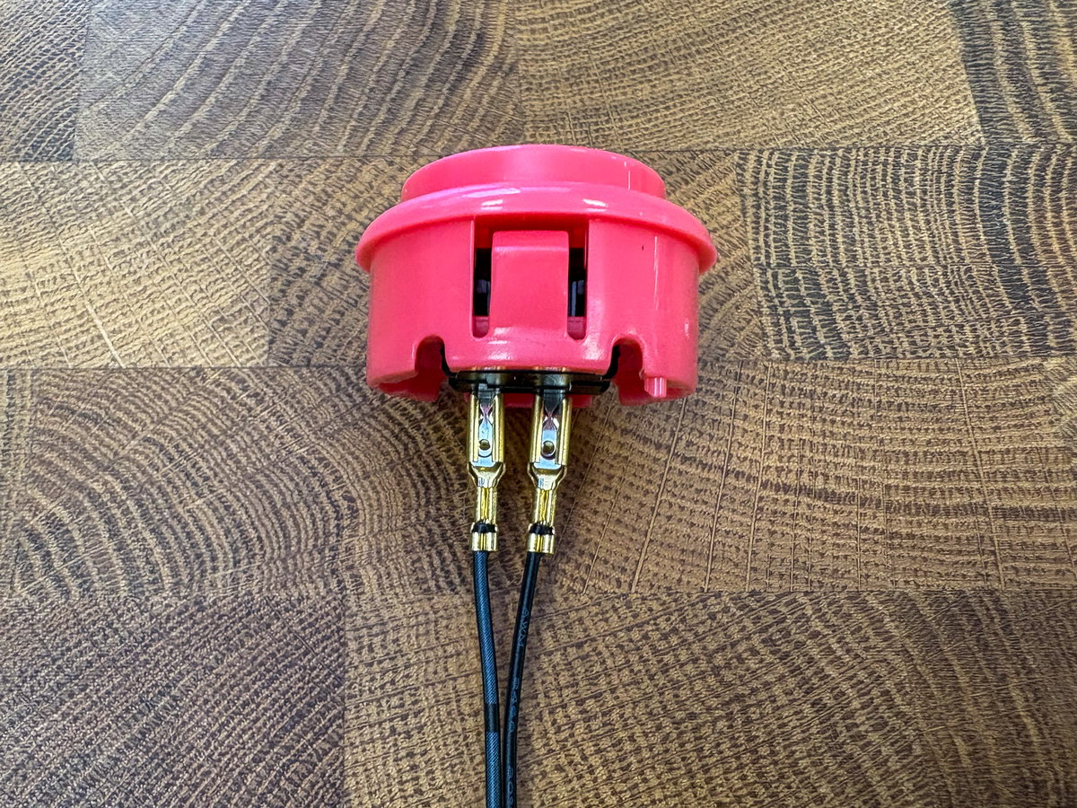
Then repeat until all the buttons have wires attached.
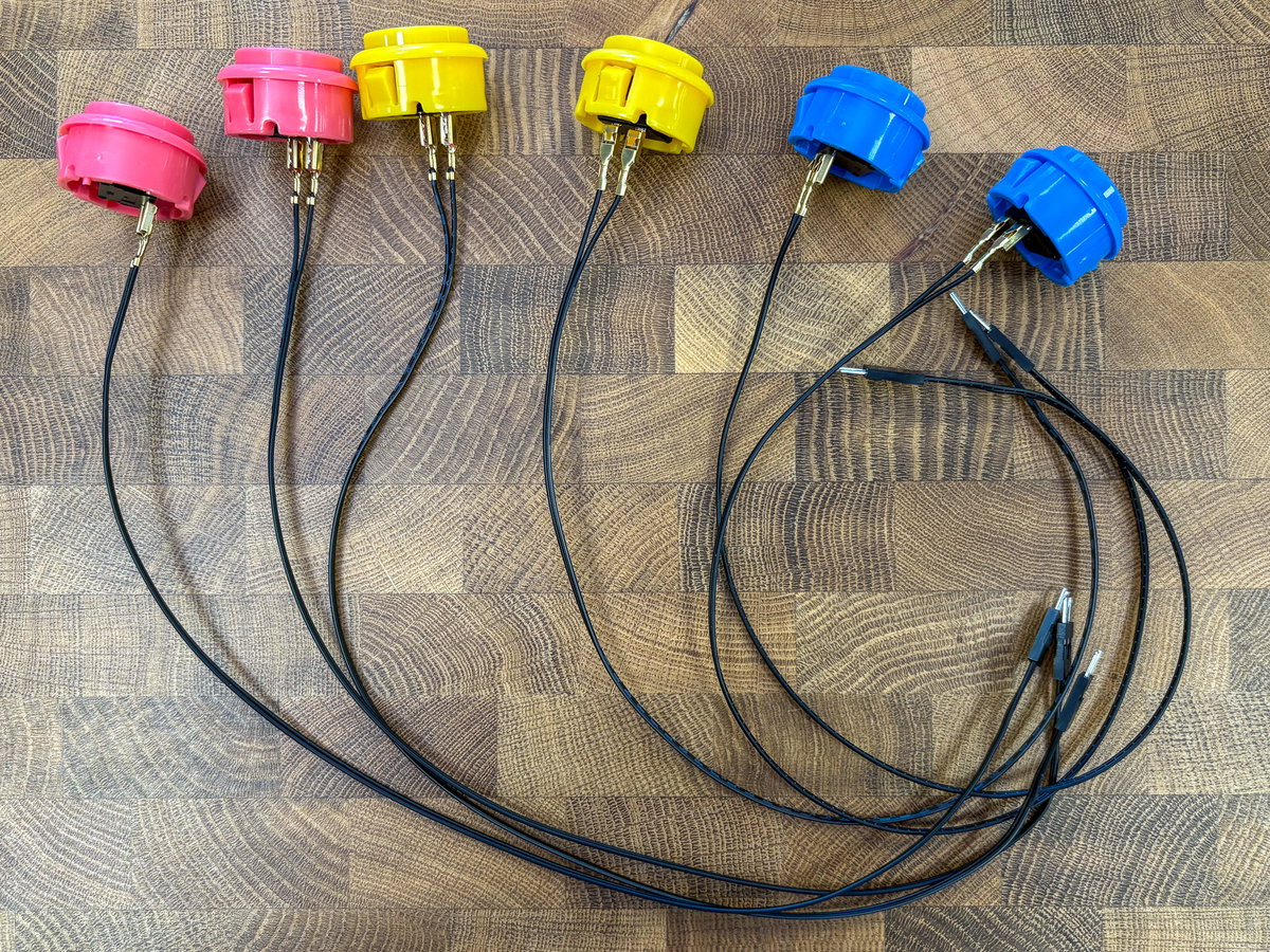
Grab a button and thread the wires, then the button through one of the holes in the console, from the top.
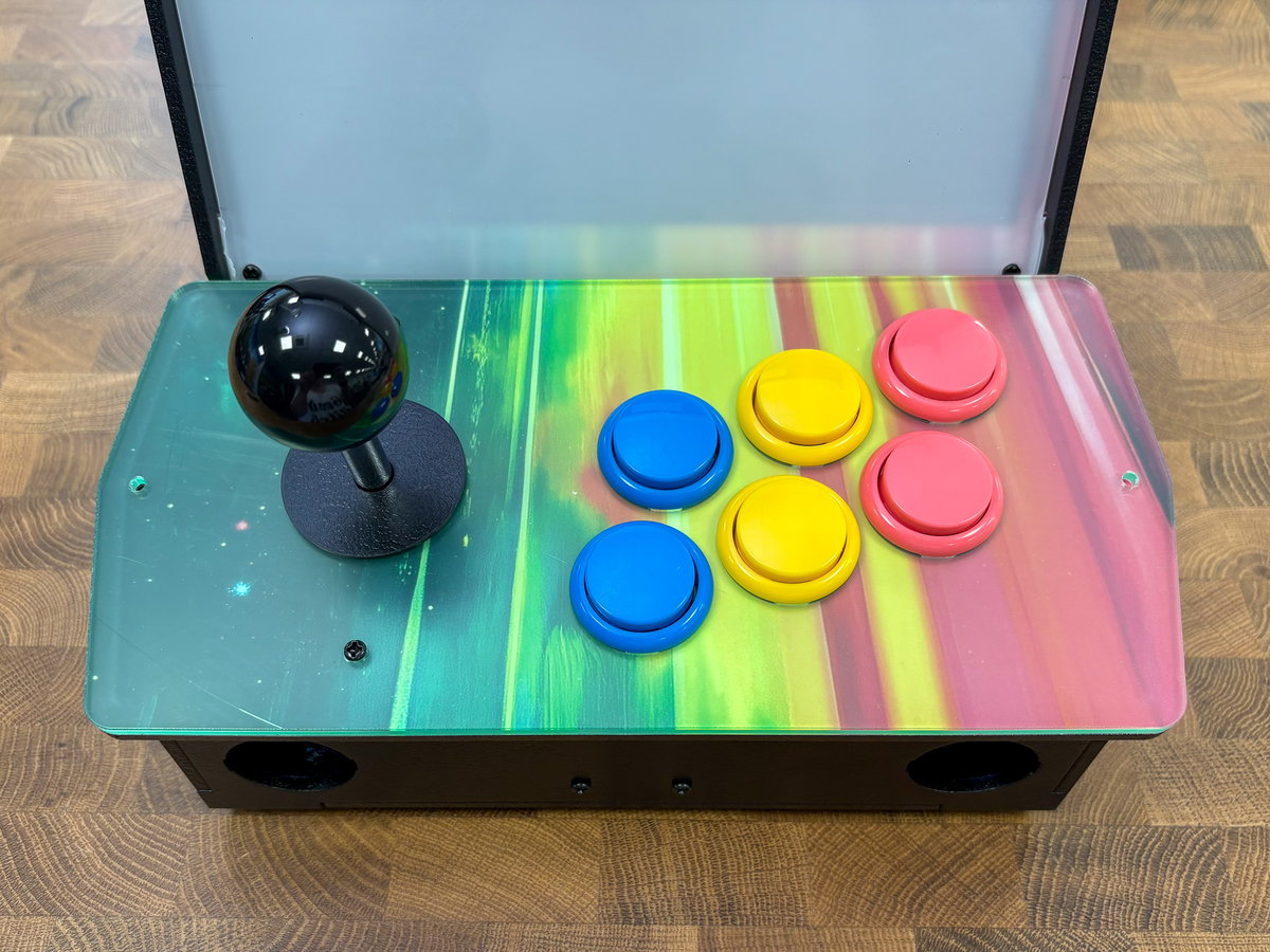
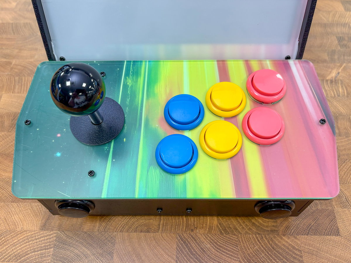
The canon arrangement of button colours is blue on the left, yellow in the middle and pink on the right to match the artwork, but feel free to arrange them however you wish.
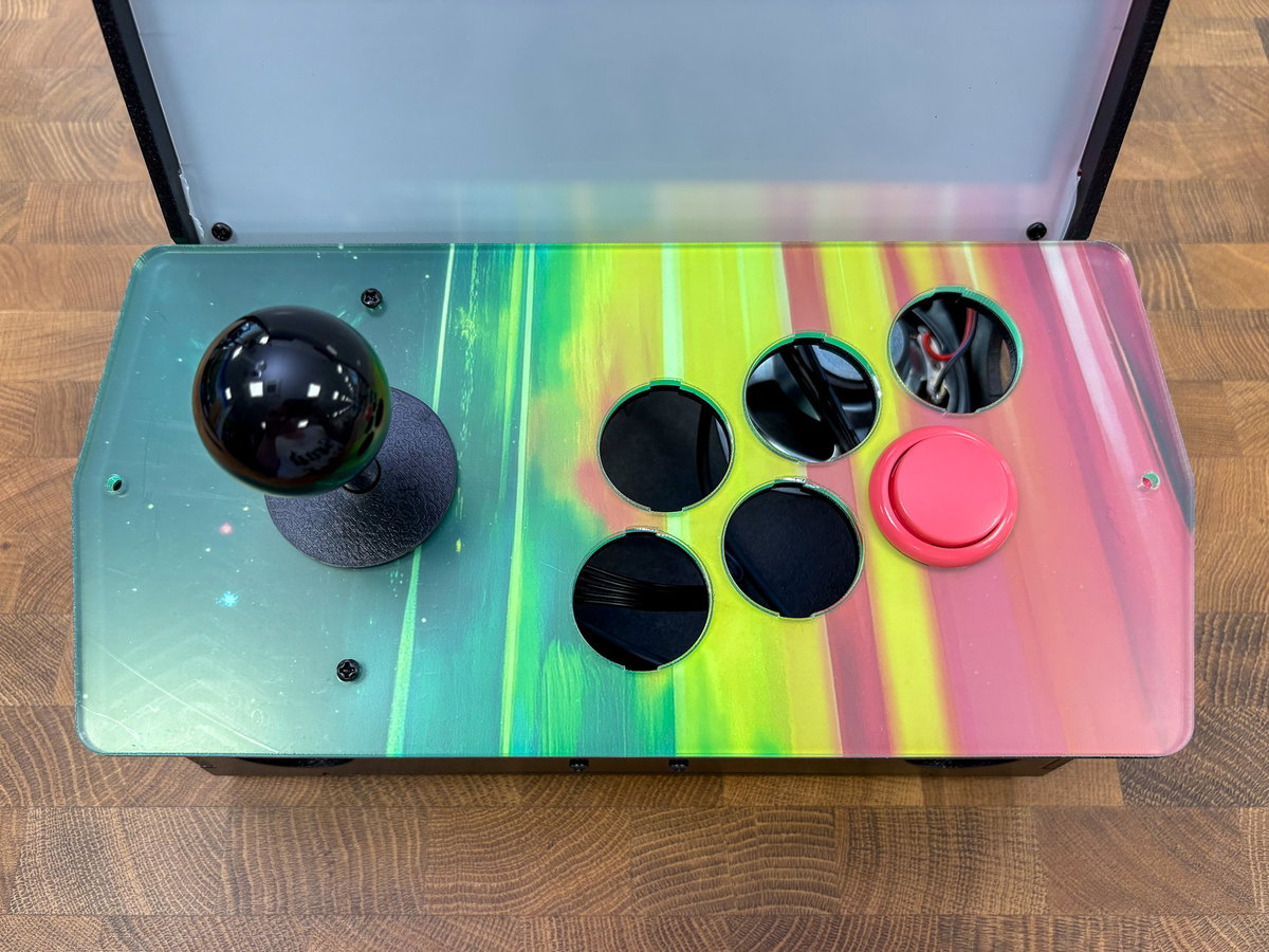
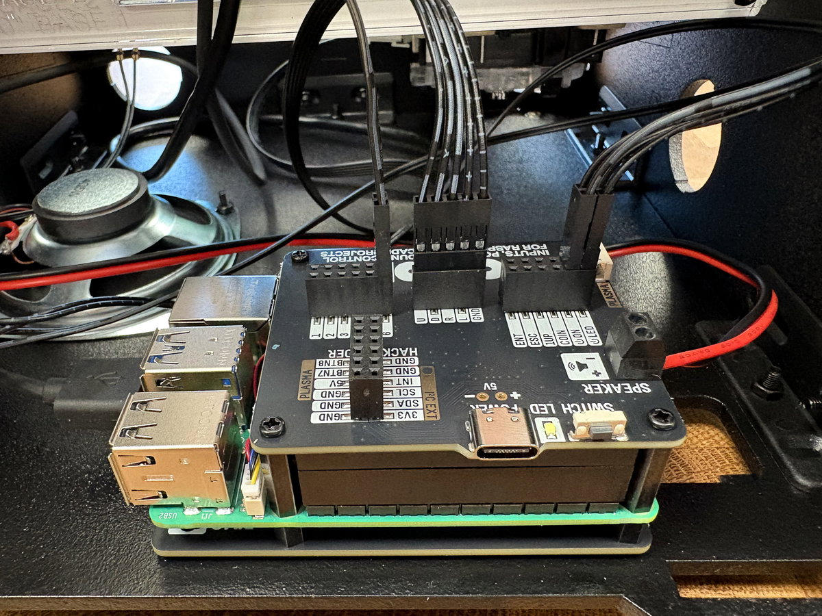
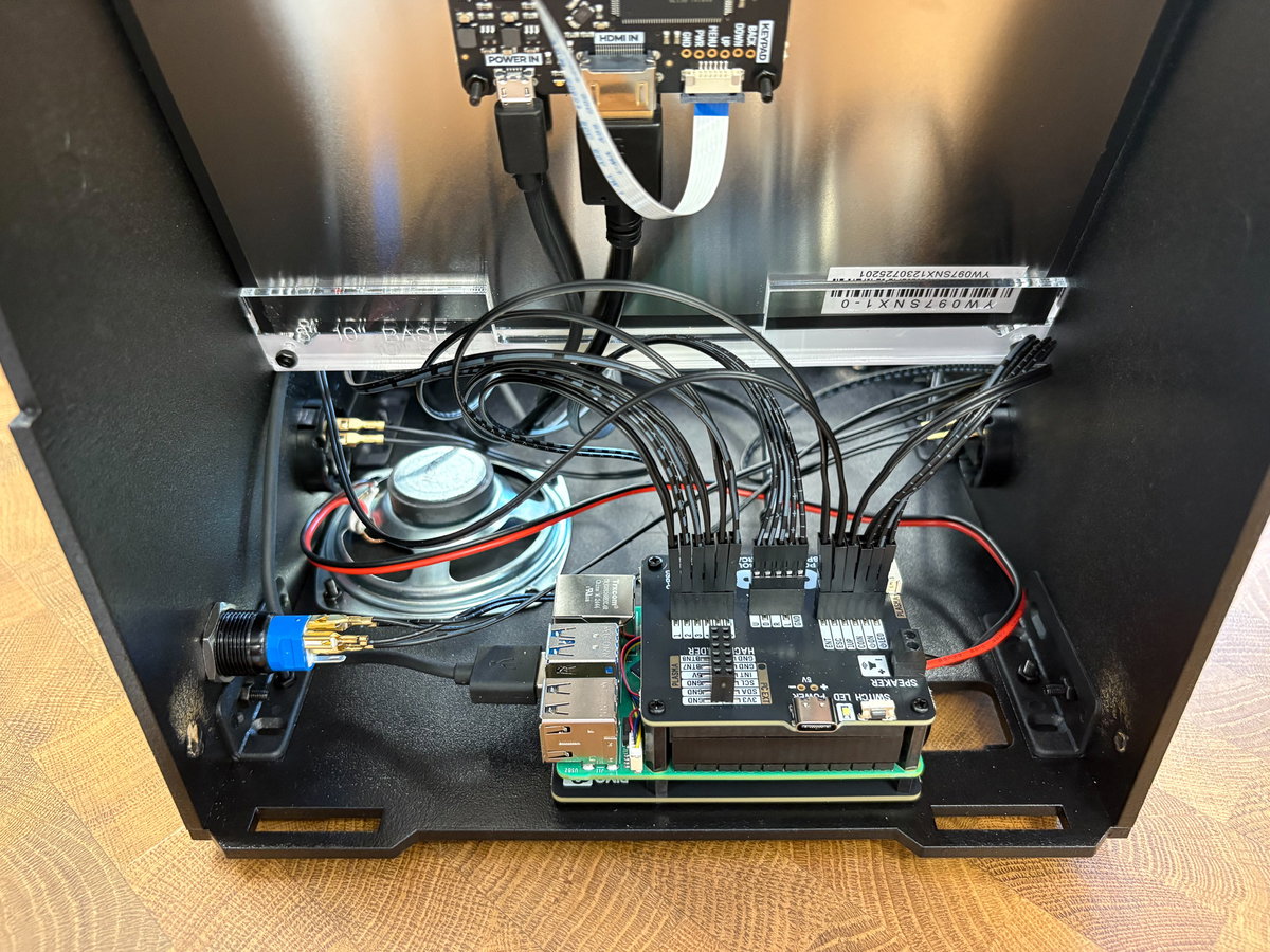
Thread the wire through to the front of the cabinet, and plug the end with the pins into one of the connectors marked 1 to 6 on the Picade X HAT. It doesn't matter too much which one, as we'll be remapping the inputs in software later on.
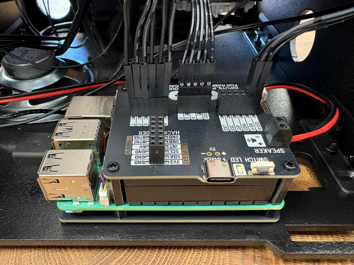
Repeat this process for the other five buttons!
Wiring the front and side buttons
For this step you'll need:
- 4x black arcade buttons
- 4x more pairs of wires from the wiring loom
Attach wires to the black buttons as before.
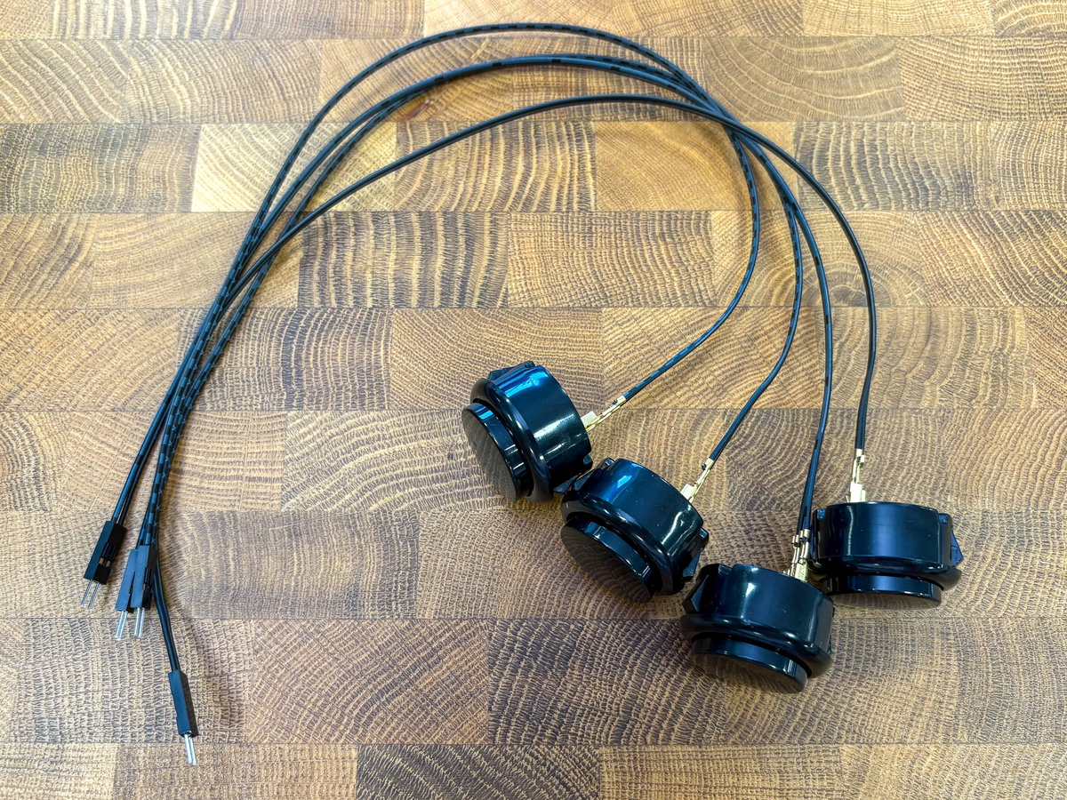
Two of these buttons go through the holes in the front of the case, and the other two go through the holes in the sides - here we're wiring up the one of the front buttons.
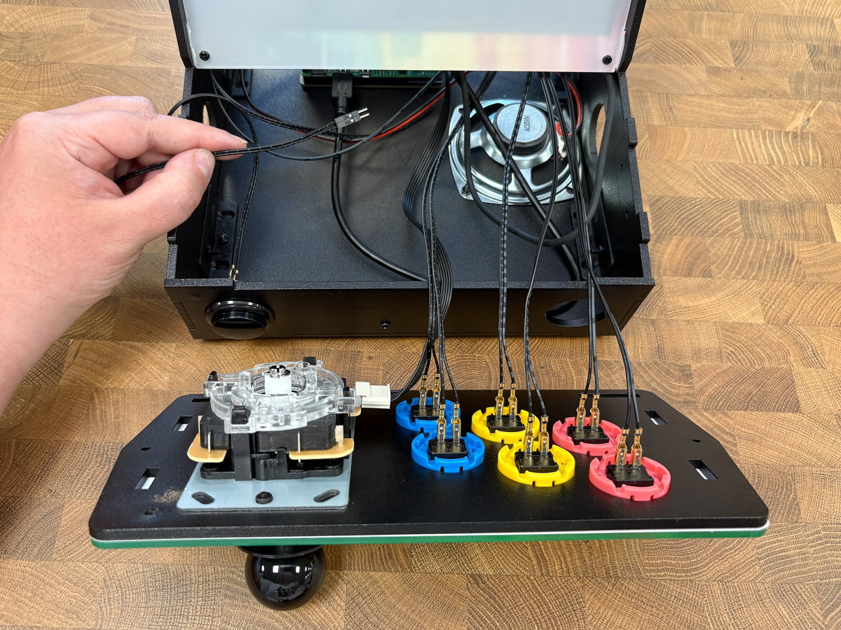
On the Picade X HAT end, you'll need to plug these buttons into ENT, ESC, 1UP and COIN (again, the order doesn't matter too much as we'll be remapping the keys in software).
Once all the buttons are wired up, flip over the console assembly and do a quick check that all the spades are securely attached to the buttons, and that none of the metal parts are touching. It will be harder to access the underside of the buttons once the console is fastened in place.
Finishing cabinet assembly
Attaching the console
You're almost done with the build!
Once you've made sure that everything is correctly connected up, it's time to attach the console to the rest of the cabinet. You'll need:
- 2x black plastic brackets
- 6x M3 screws
- 6x M3 bolts
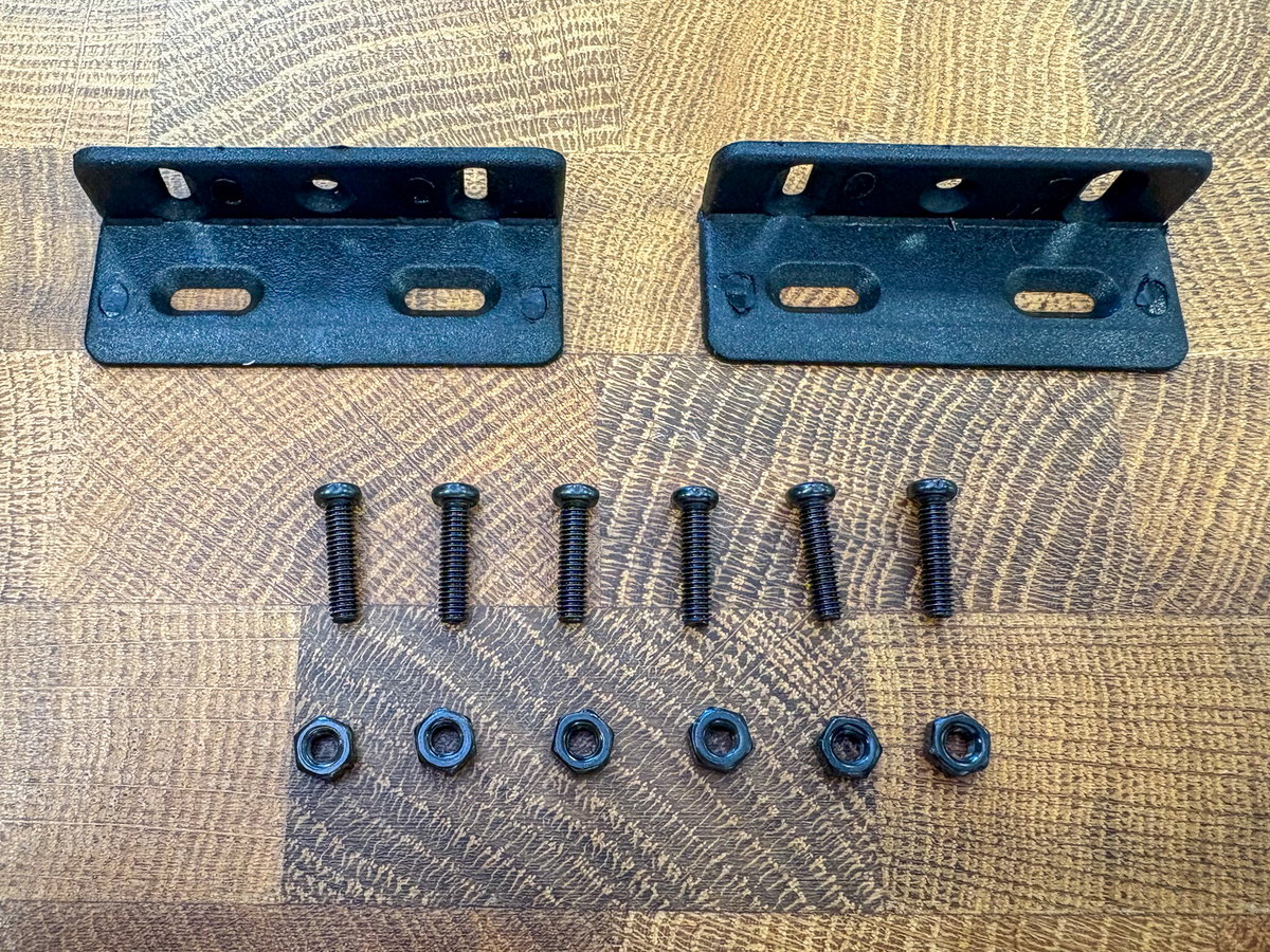
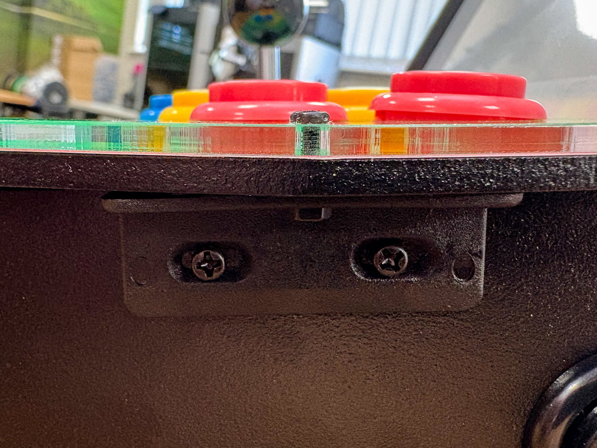
Attach the two remaining brackets to the outside of the cabinet with M3 nuts and screws, with the side of the bracket with three holes pointing upwards. It's worth leaving these fixings a little bit loose, until you've attached the bracket to the console assembly.
Slot the console assembly into place on the tabs on the front of the Picade. The buttons should be on the right, and the stripes on the screen assembly and console assembly artwork should match up. Fix the console assembly in place with two more M3 screws and bolts, one on each side.
Fitting the back panel
Just one thing left to do - put the back of the cabinet on. You'll need:
- 1x wooden panel F
- 1x rubber O ring
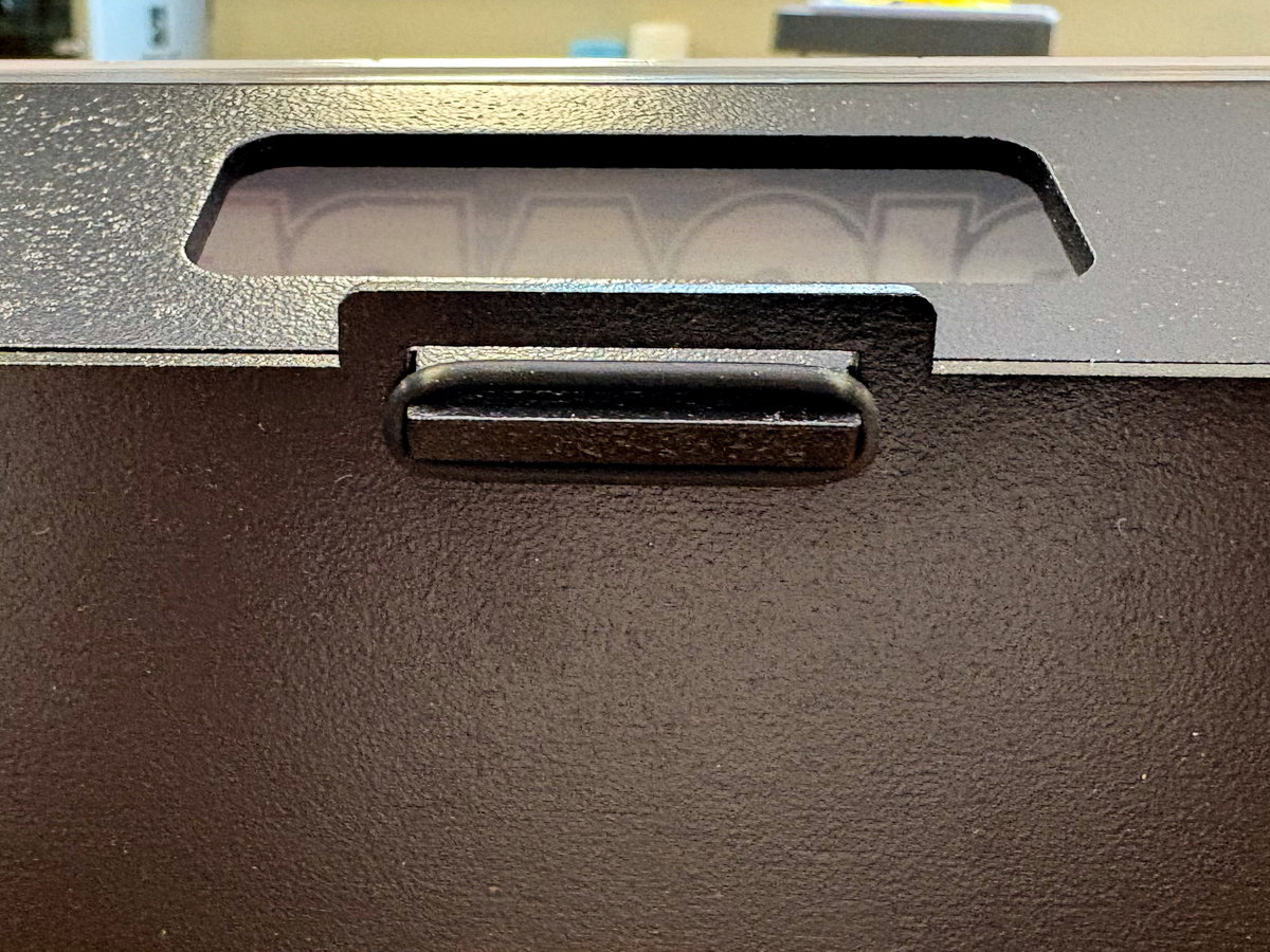
With the good side facing outwards, slot the two tabs at the bottom of panel F into the slots at the base of the cabinet, and the protrusion on panel C into the slot at the top - you might have to flex the top of the cabinet slightly to get it in.
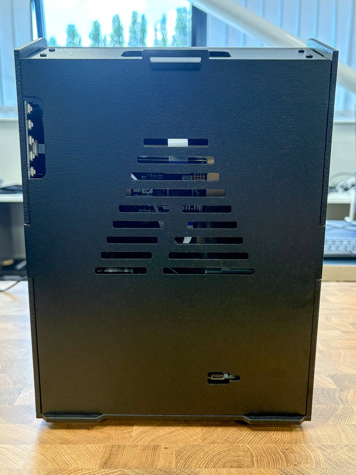
Pop the o-ring over the protrusion to keep everything in place.
Peeling off the protective film
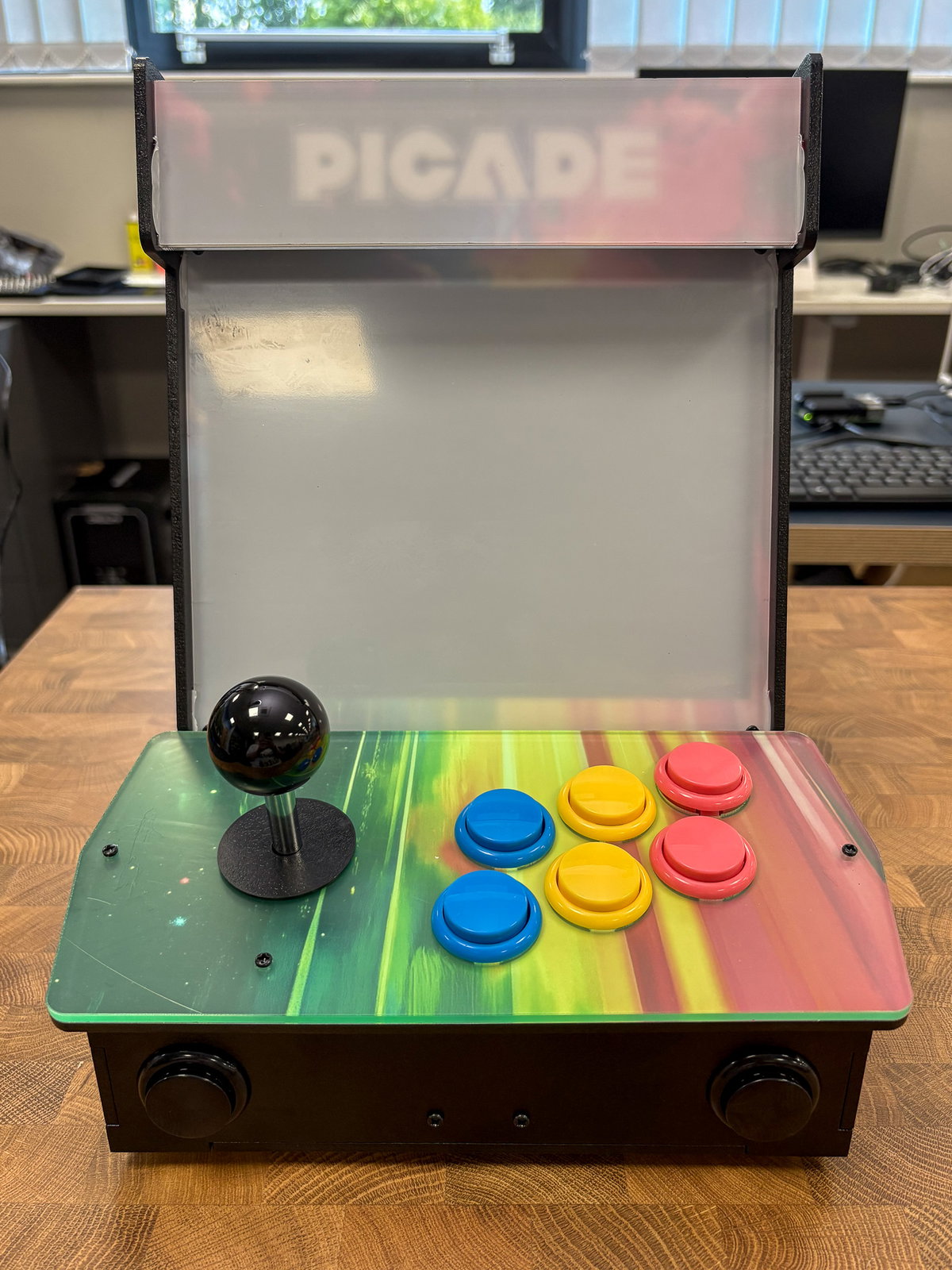
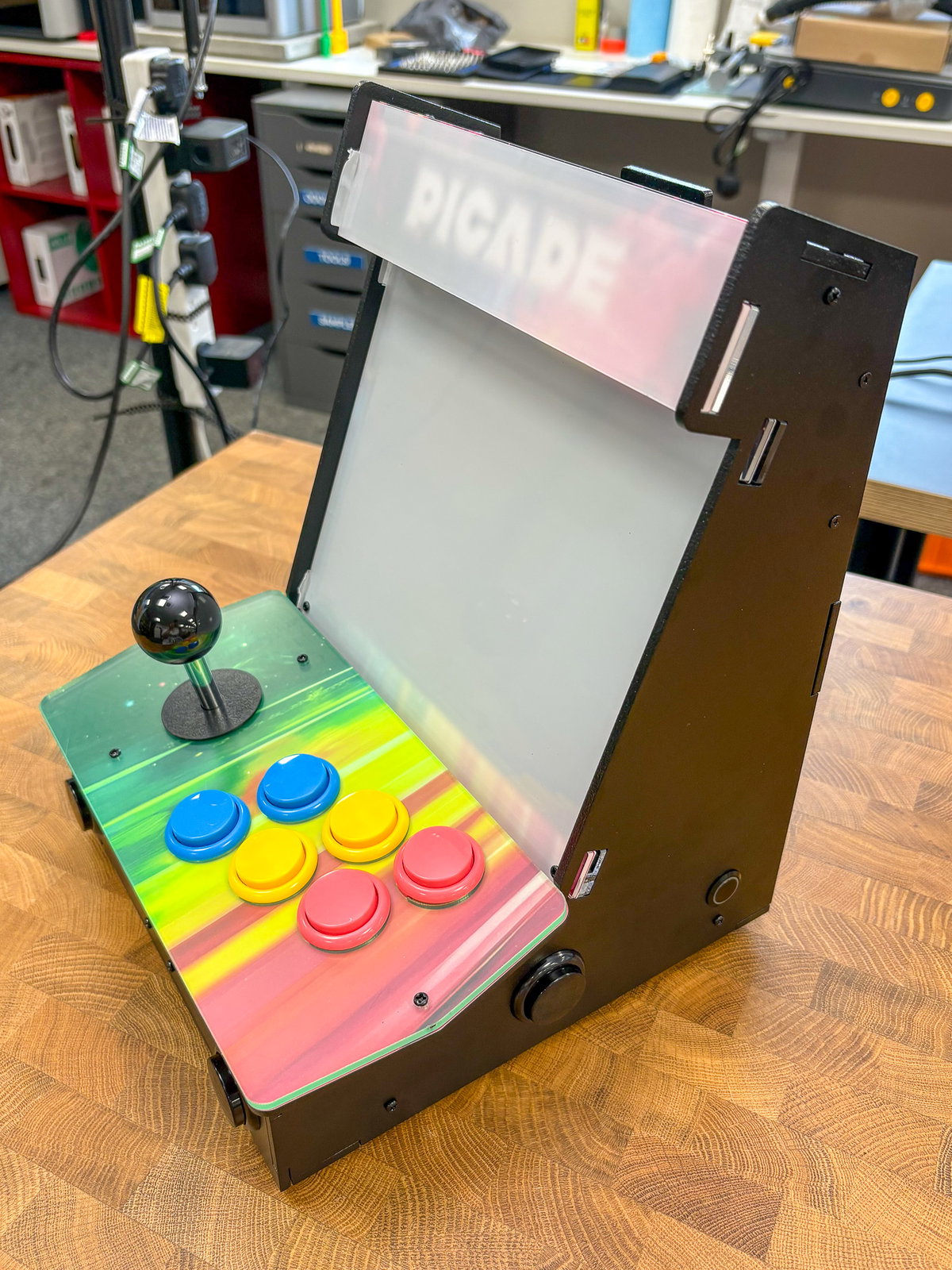
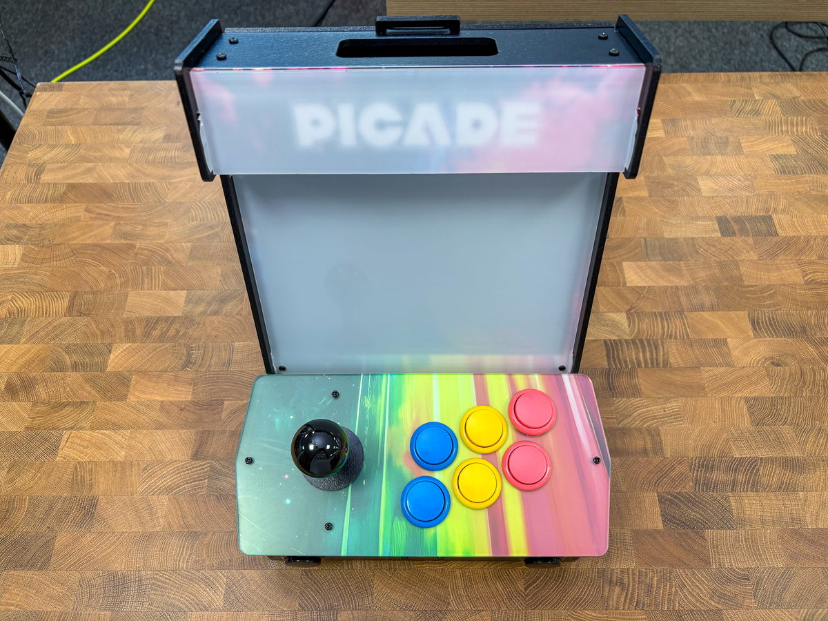
Build done!
Next steps
We hope you enjoyed building your Picade! When you're ready, go to our software guide for instructions on how to set up RetroPie on Raspberry Pi 5.