Assembling your Trilobot
Trilobot is a mid-level, expandable, learning-friendly robot with sweet underlighting and lots of example code to get you started. This tutorial will show you how to put everything together, how to install the Trilobot library and run the examples - you'll be zooming around in no time!
What you'll need
- A Trilobot kit - we do a Base Kit and a Full Kit! If you have the Base Kit, then you will also need:
- A Raspberry Pi 4 - any flavour will work. If you want to use an older Pi with this kit that's also possible (as long as it's one of the ones with a 40 pin header), but you'll need to pick up a different power cable.
- A Raspberry Pi Camera v2 or v3 (Base Kits shipped from February 2023 onwards include updated PCBs that will accommodate a v2 or v3 Camera Module).
- A microSD card
- A USB-C power bank
With both the Full and Base Kit, you'll also need the following, which aren't included in the kits.
- A micro-HDMI to HDMI cable or other means of connecting your Pi to a display.
- A HDMI monitor.
- A USB keyboard for installing the software and programming Trilobot.
- A USB mouse for interacting with graphical elements of the Raspberry Pi OS.
- For charging your power bank you will also need a USB-C power supply like this universal one or the official Raspberry Pi one (if you go for the official one, make sure you pick the correct power supply for your region).
Preparation
It'll take an hour or so to build your Trilobot. Make sure you have sufficient build space to put everything together without bits rolling off and getting lost. You’ll need a small Phillips screwdriver (or, if the effort of turning a screwdriver manually seems too old school, a Wowstick).
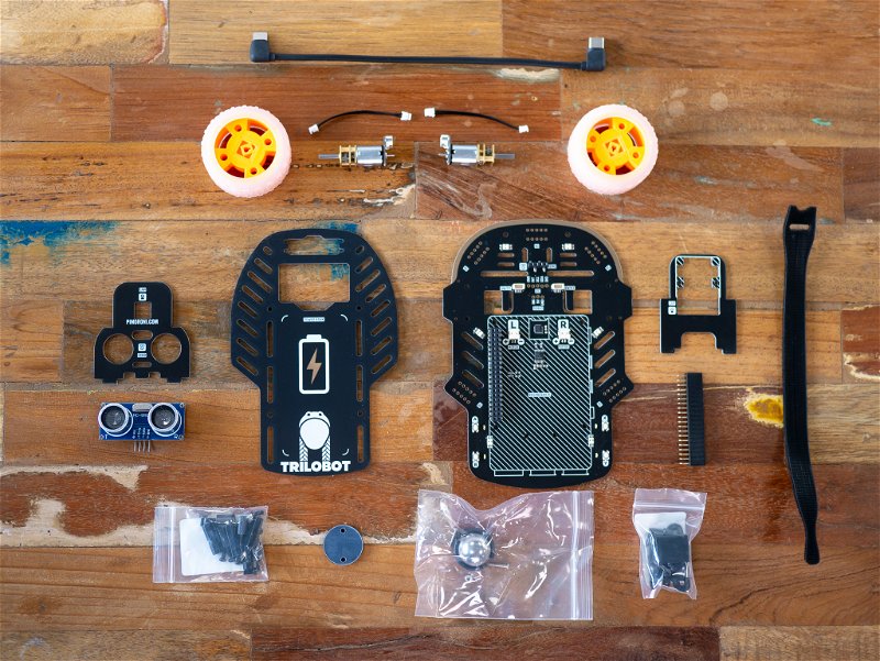
Here's a complete list of everything that's inside each kit. If you're missing anything, drop the support ninjas an email at support@pimoroni.com and they'll sort it out.
Base kit
- Trilobot main chassis board (big PCB with all the LEDs and other components, identifiable from its fancy gold bumper).
- Trilobot top board (big PCB with a picture of a battery on top and oodles of gold triangles on the underside).
- Trilobot front board (small PCB that looks a bit like a face wearing a bowler hat. Has ECHO and PIMORONI.COM printed on the front).
- Trilobot camera board (small PCB with CAM CABLE printed on the back).
- 2 110:1 micro metal gearmotors with pre-soldered shims
- 2 grippy orange wheels
- 2 short motor cables (2 pin JST-ZH to JST-ZH, for the cable aficionados)
- A pair of motor brackets and fixings (in a bag labelled COM0817)
- Metal standoffs and screws (in a bag labelled Rover Standoff Set)
- Ball castor with fixings
- Acrylic spacer
- Ultrasonic distance sensor
- Booster header
- 2 Velcro cable tidies
- USB-C to USB-C cable
Full kit
In the Full Kit, you'll get everything in the Base Kit plus
- Boxed Raspberry Pi 4
- Boxed Raspberry Pi Camera v2 (with cable).
- USB-C power bank
- MicroSD Card (with Raspberry Pi OS pre-installed).
Assembly
Adding the motors and wheels to the main board
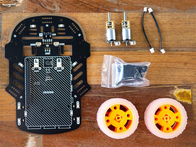
To start, you'll need to find the Trilobot main chassis board and remove it from its anti-static bag - this board is the base of your Trilobot and it's where all the action happens. You'll also need all the motor gubbins: two micro metal gearmotors with attached shims, two black plastic motor brackets, two short motor cables, and a pair of orange wheels. The whole set should look like this:
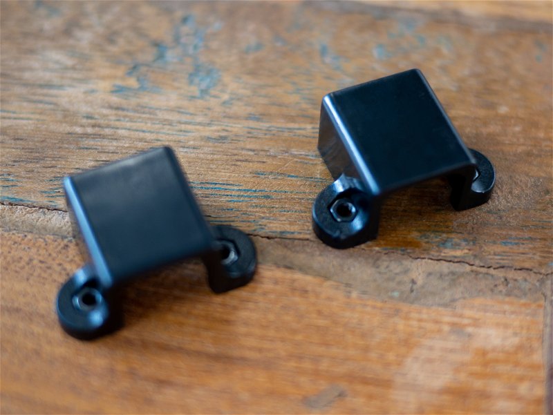
Empty out the motor bracket bag. From it take a motor bracket and insert a nut in either side. This can be a tight fit so you may need something (such as a flat-head screwdriver) to help you push the nuts in. Do this for both motor brackets.
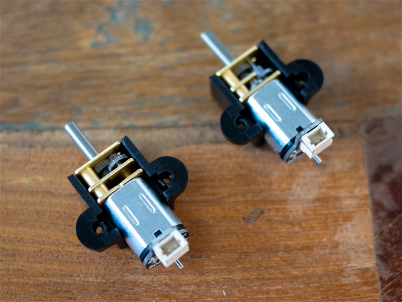
Flip the brackets over and insert the micro metal gearmotors, like so:
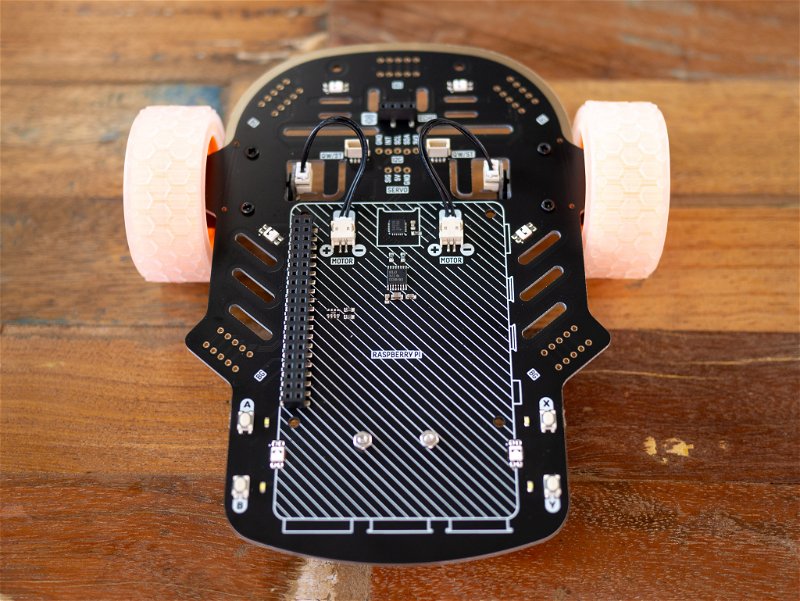
Take the longer of the two screws, and mount each motor onto the underside of the Trilobot main chassis board. The underside is the side of the board with the Trilobot logo and name, not the side with the Raspberry Pi outline.
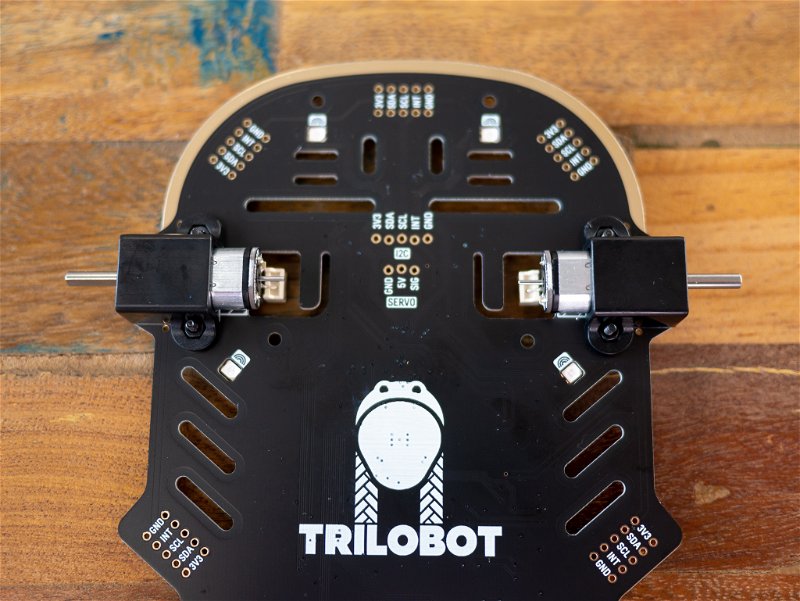
You should be left over with a few screws and nuts. This is fine. These are extras in case any go missing :)
Next, take the two short motor cables and plug them in, connecting the motor shims and the main board. Take the two grippy wheels and push them onto the axles of the two motors. These can be quite stiff so might need a bit of force.
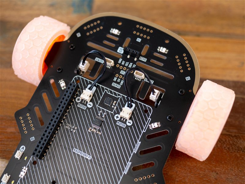
Adding the castor to the main board
That's it for the motors - now it's time to add the castor which acts as the robot's 'rear wheel'. Find the bag with the castor and its associated nuts and bolts, and the round black acrylic spacer.
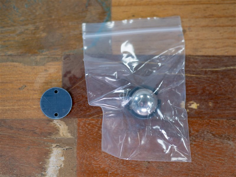
Remove the protective film from the spacer. Pop the castor out of its plastic housing - if you're struggling to get a grip a small flathead screwdriver can help with this.
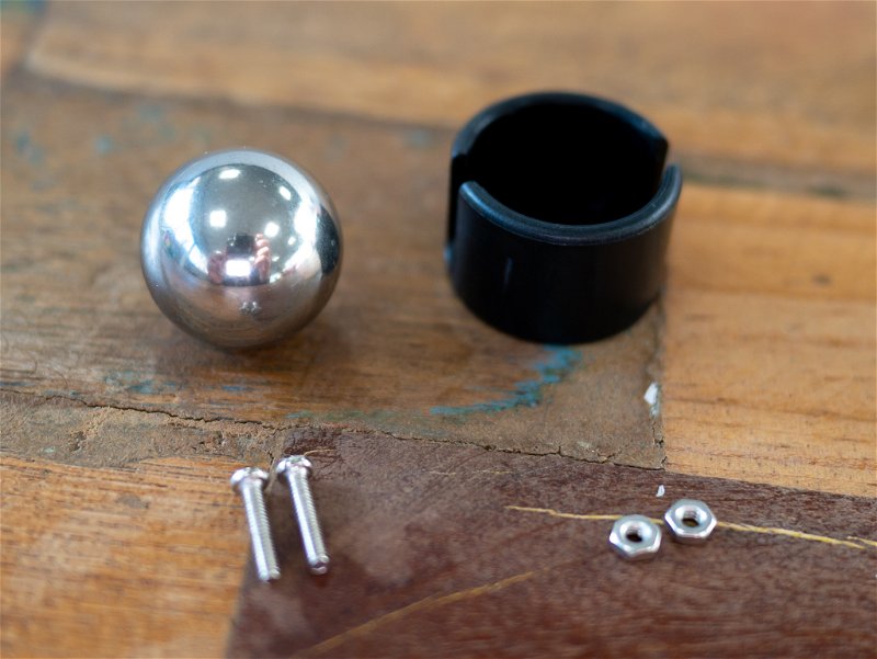
Poke the long silver screws that came with the castor and into the plastic housing, like this:
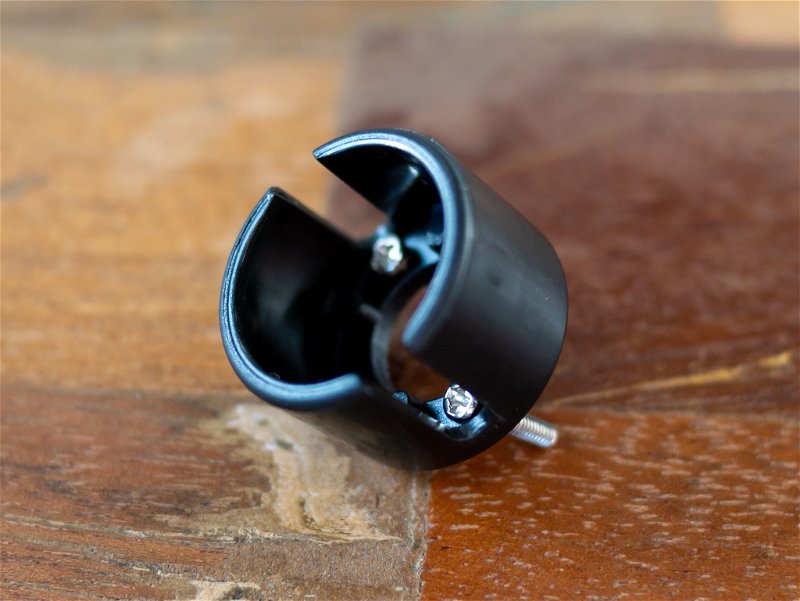
Slot the spacer over the sticking out ends of the screws.
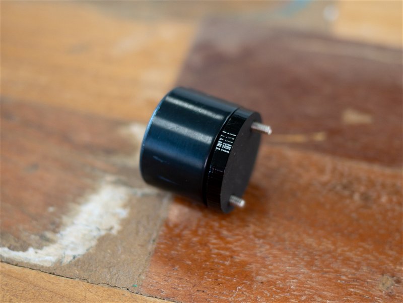 Then insert the screws through the holes on the underside of the Trilobot main board - you'll see where it's meant to go from the board markings. Take the silver nuts and screw them on to the ends of the screws, then tighten everything up!
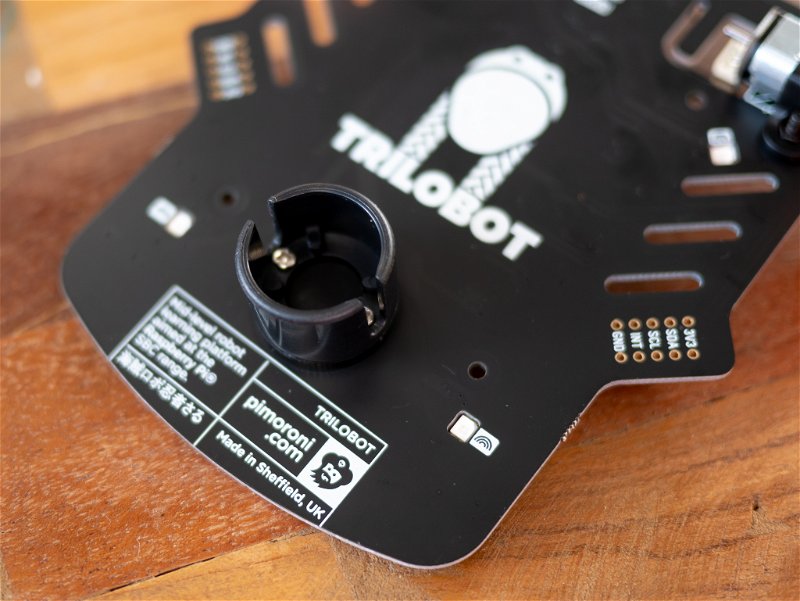
Finally, re-add the castor ball to the housing. This can require some encouragement - you will hear and feel a solid clunk when it is successful.
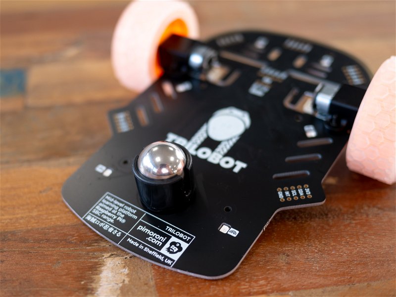
Now you have the driving section of your Trilobot assembled!
Preparing your Raspberry Pi Camera
For this stage, you will need your Raspberry Pi 4, Raspberry Pi Camera v2, Trilobot camera board, and the rover standoff set.
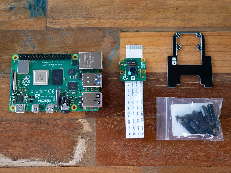
Unbox the Raspberry Pi Camera. It should come with a cable pre-attached.
Grab the Trilobot camera board and feed the camera through its large cutout from the side that says CAMERA CABLE to the side that says CAM.
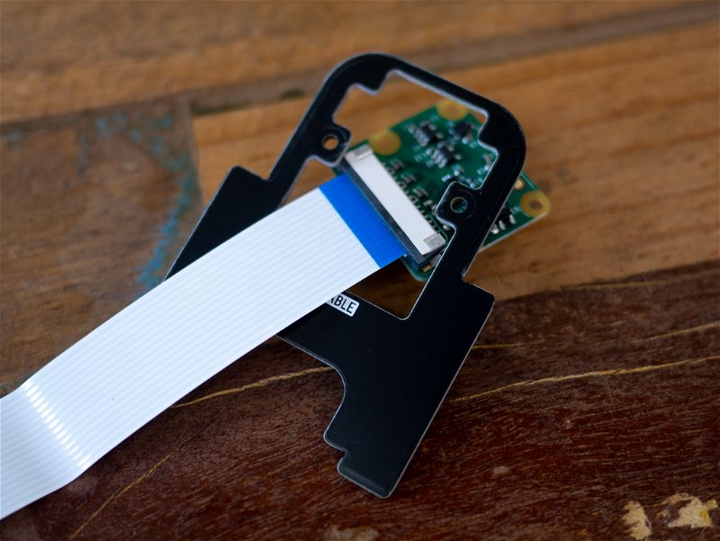
Lay the camera down, so that its board fits into the hashed area, like so:
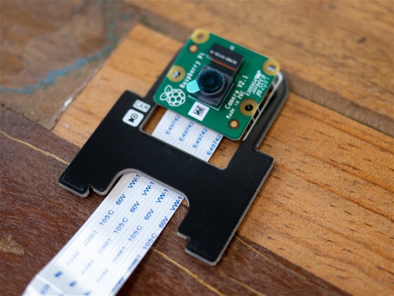
In the rover standoff set you will find some very small M2 nuts and bolts. Use them to attach the camera to the camera board. Do this by inserting the screws from the CAM CABLE side so they stick up out of the front side of the camera.
Then, take the M2 nuts and screw them on to the front. You should now have an assembly that looks like this:
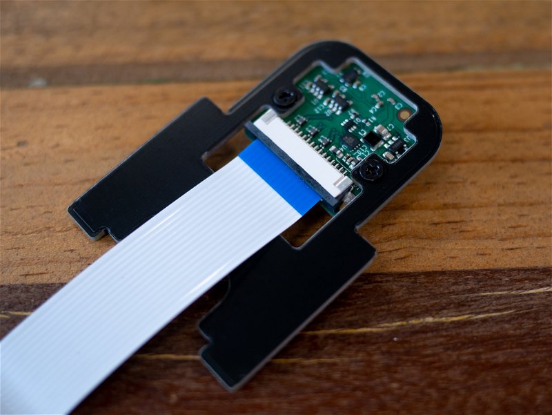
Next, get out the Raspberry Pi 4, take the free end of the camera cable, and connect it to the Pi. You can open up the camera connector by gently pulling the grey part upwards slightly. Poke the cable into the connector with the blue side of the cable pointing towards the Pi's USB ports, and then push down the grey bit of the connector down to lock it in place. The camera connector is the one in the middle of the Pi - don't be lured in by the display connector at the other end that is very similar!
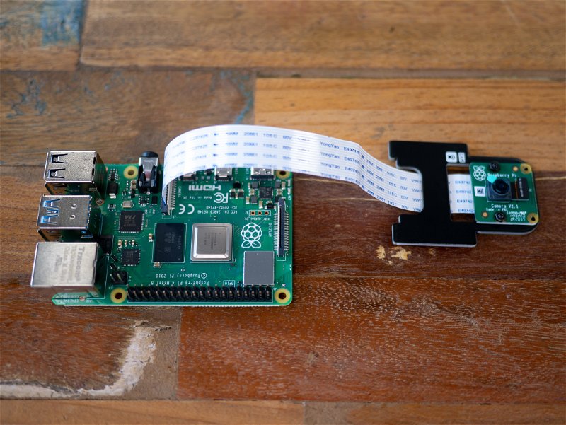
Mounting your Raspberry Pi
For this, you will need the Trilobot chassis assembly, Raspberry Pi 4 assembly, booster header, and the rover standoff set.
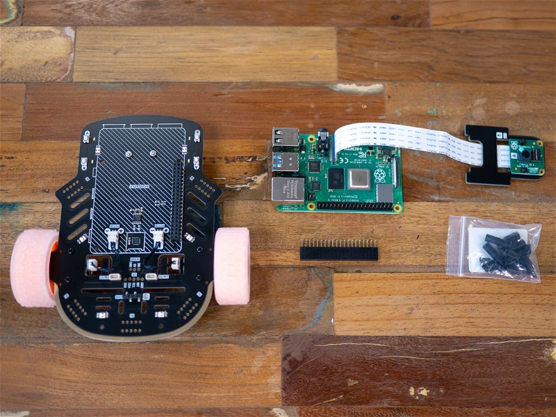
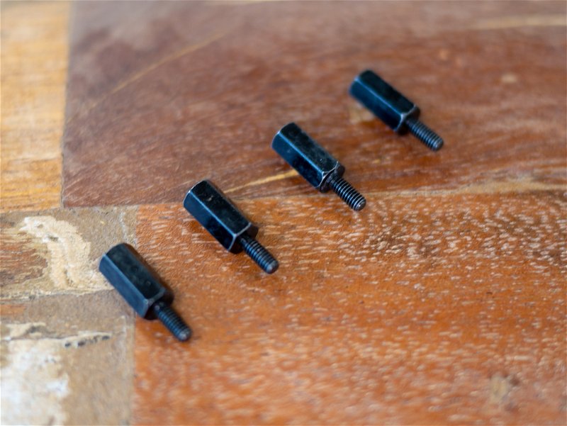
From the rover standoff set take 4 of the M2.5 screws and the 4 long standoffs.
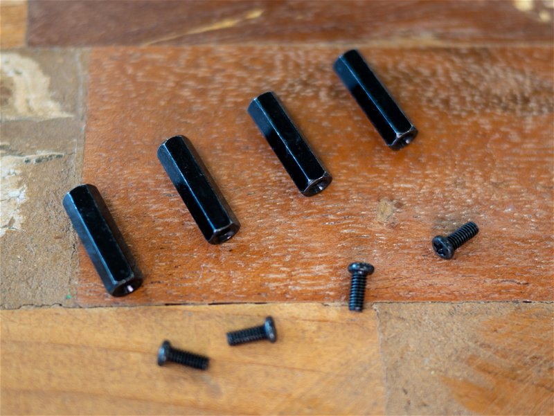
Mount the standoffs to the Trilobot main chassis assembly using the screws, so that they are sticking up out of the Raspberry Pi outline.
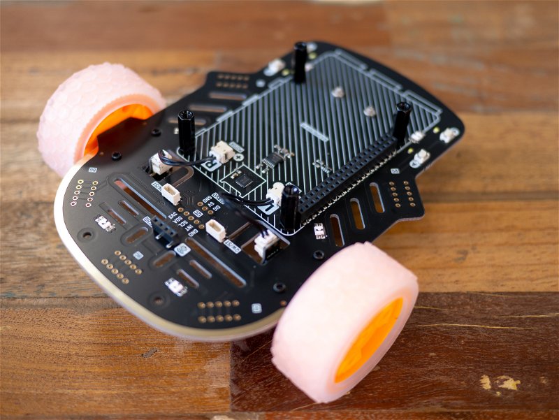
Take the booster header and plug it into the matching socket header on the Trilobot main chassis assembly.
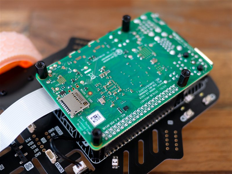
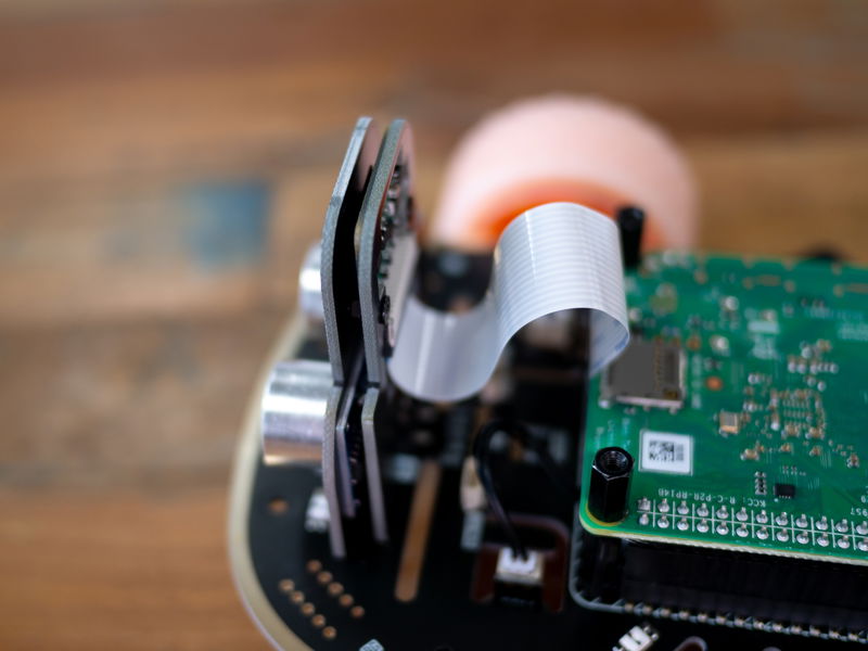
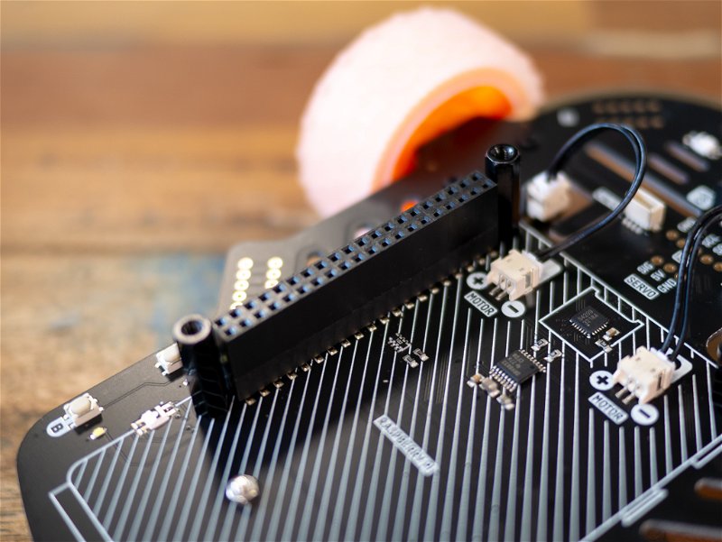 Then take the Raspberry Pi 4, flip it upside down, and plug it into the booster header with the USB and Ethernet ports at the back of the robot. The camera cable should be dangling over the front of Trilobot.
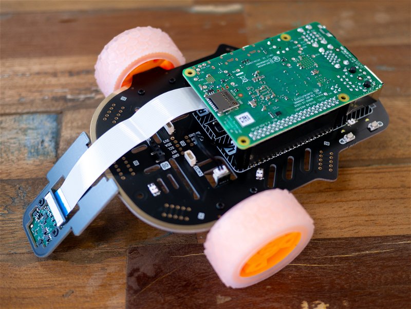
To secure the Raspberry Pi 4, take the 4 shorter standoffs from the rover standoff set and attach the ends with the screw threads through the Pi into the standoffs you installed earlier.
Assembling the front
For this bit, you will need the Trilobot front board, ultrasound sensor, and the Trilobot chassis assembly.
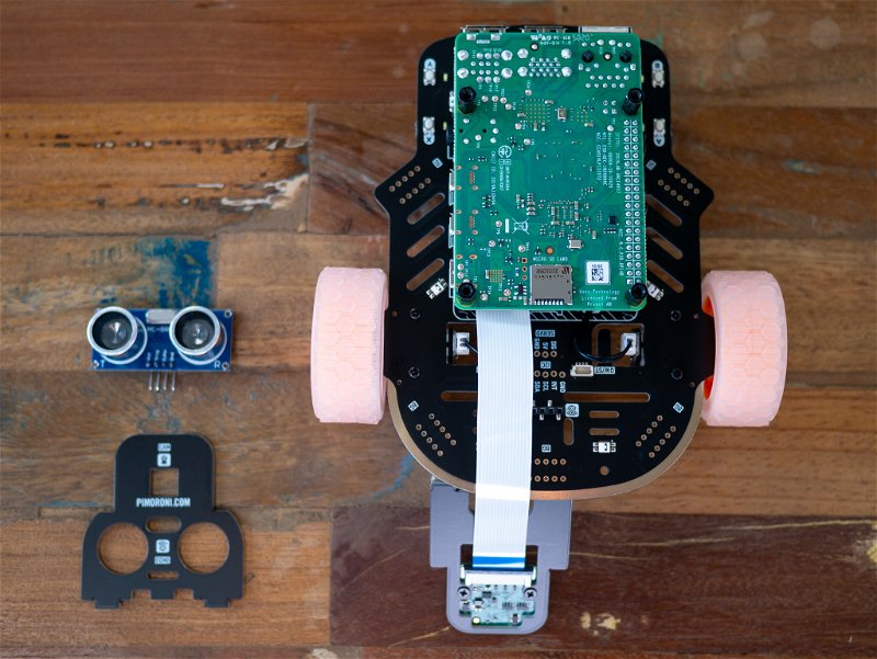
Take the ultrasound sensor and insert it into the Trilobot front board, covering the hashed area.
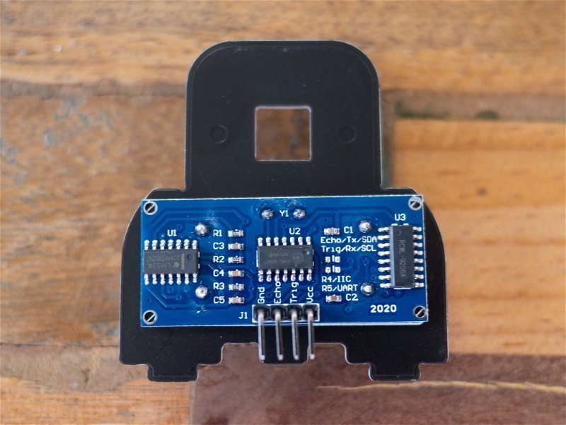
Then, holding both together, plug the ultrasound sensor into the connector labelled ECHO on the Trilobot main chassis board.
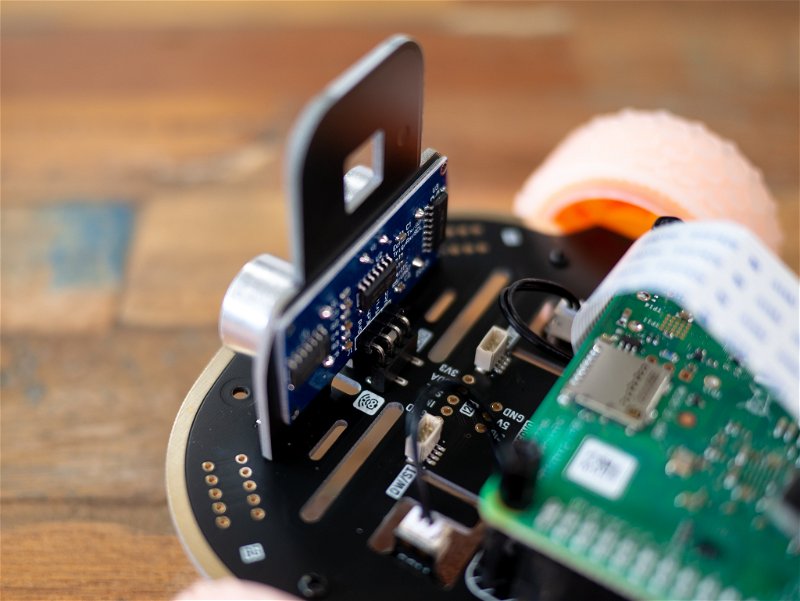
Wiggle the Trilobot front board around until it aligns up with the slots in the PCB and push down.
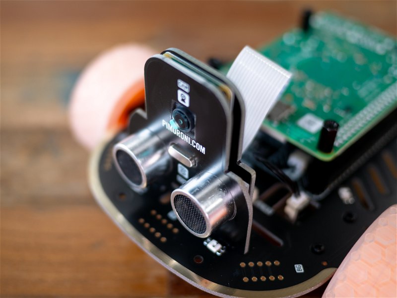
Once done, your assembly should look like this. Now it has a face!
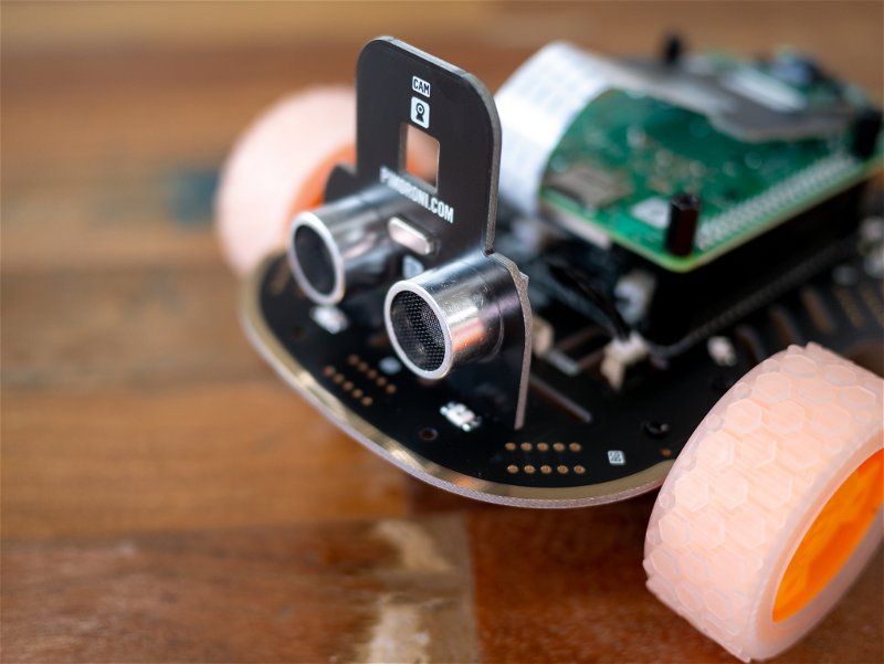
Take the camera assembly and insert the bottom tabs into the slots on the main board that are just behind the ultrasound sensor. Push it forward so the camera goes inside the square hole on the Trilobot front board.
Mounting the battery
Nearly there! For this step, you will need the Trilobot top board, your USB-C power bank, and the two Velcro cable tidies.
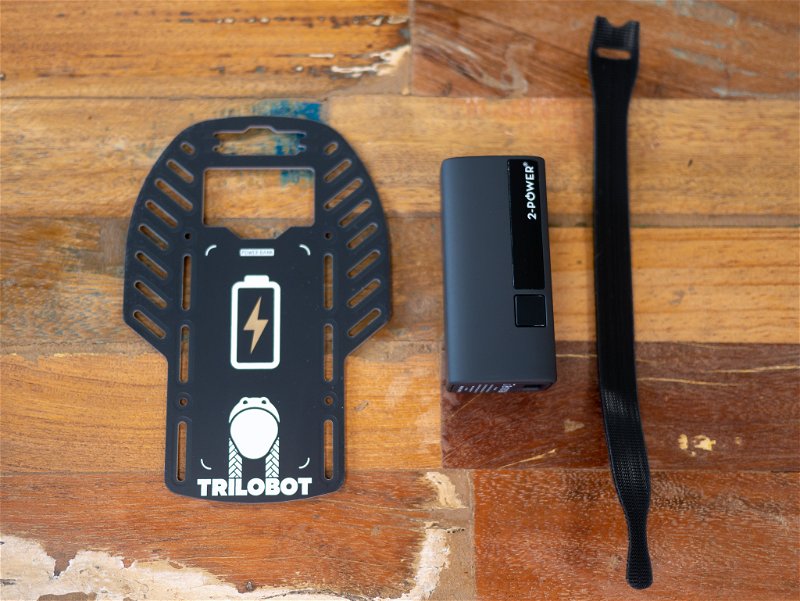
First, you need to choose which side you want of the top board to be visible. We will be showing you with the Trilobot logo side on top (but we're rather fond of the glitzy Triangular pattern side too).
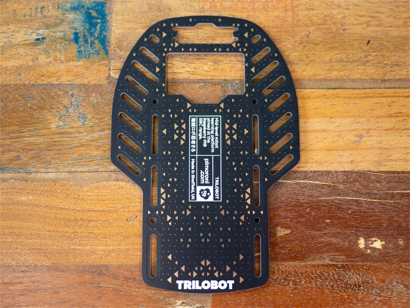
Take the Velcro cable tidies and the top board. Feed the ties through the long slots from the top side, around the under side, and back up to the top side. We recommend doing this with the soft fabric side facing towards the board, to avoid scratches to it and your battery bank.
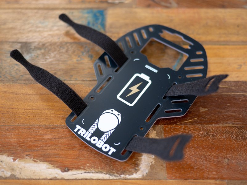
Now, take your battery bank and place it in between the open Velcro ends on your top side, with the USB-C output facing the front. If you're using the battery bank that's included in the Full Kit, this will have the power button be on the right. The Trilobot logo side of the top board has a handy outline showing where your battery bank should go.
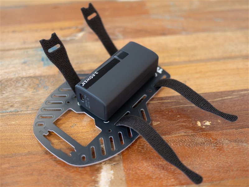
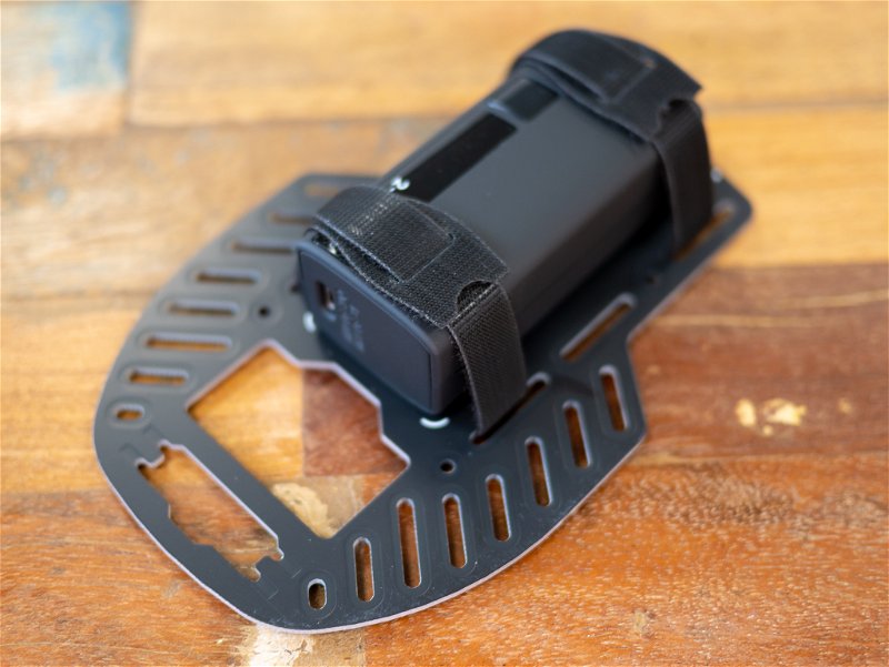
Poke the tie ends through the slots and fold them over the battery bank to hold it in place. Be sure to do this tightly so that your battery bank won't slide around as your Trilobot moves.
Adding the Top
For the last stage you will need the Trilobot chassis assembly, the Trilobot top assembly, the USB-C power cable, and the remaining M2.5 screws from the rover standoff set.
Take the USB-C power cable, and plug one end into your Raspberry Pi 4's power connector.
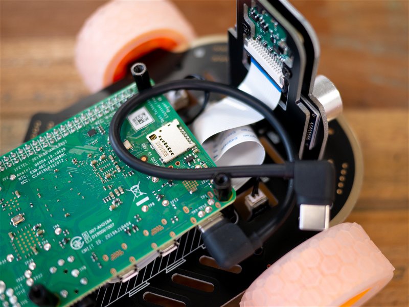
Feed the other end of the cable through the large hole in the underside of the Trilobot top board and line up the front slot with the now vertical front and camera boards.
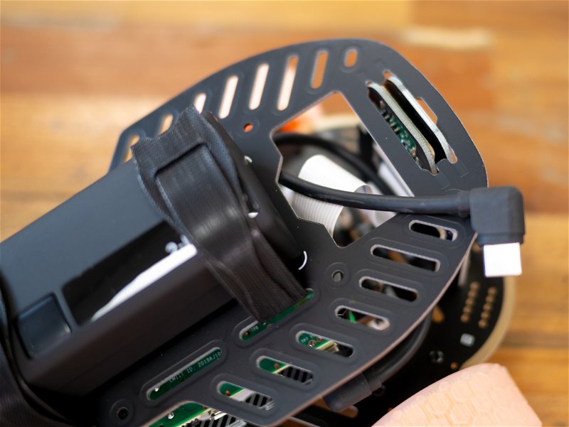
Push the top board down over the front and camera boards to lock them in place. This can be a tight fit, so may require some gentle side-to-side rocking of the top board to push it down. You should be left with something like this.
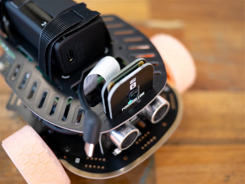
With that pushed down, feed the excess USB cable down into the gap between the Raspberry Pi 4 and the Trilobot top board.
Finally, take 4 M2.5 screws and screw down the Trilobot top board into the standoffs you installed earlier.
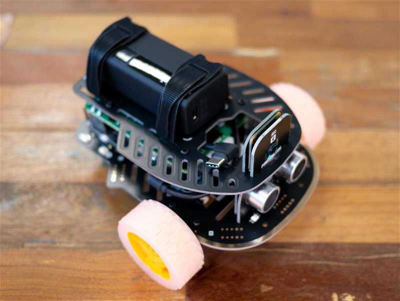
With that done, your Trilobot is now assembled. Victory snack time!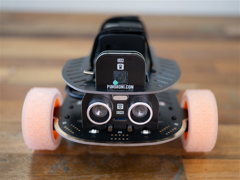
First time set-up
These instructions will assume you're programming Trilobot by attaching a USB keyboard, USB mouse, and HDMI monitor to it, but you could also set up your Pi headlessly and connect to it via SSH if you prefer.
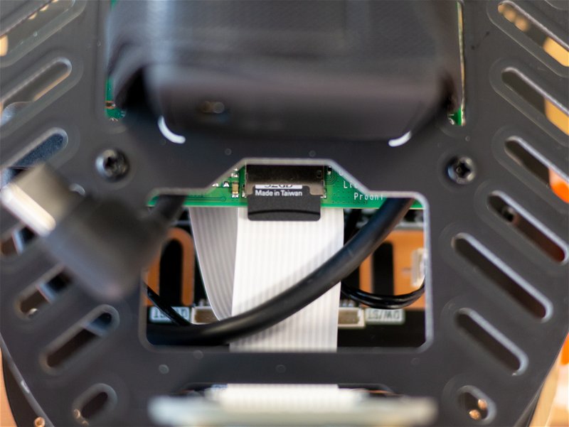
Take the microSD card, remove it from its big SD card-sized adapter, and insert it into the Pi's microSD card slot.
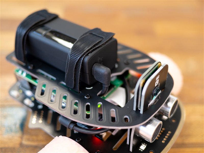
Plug in the free USB-C end of the power cable into Trilobot's power bank - this will cause the Pi to start booting.
Wait for the Raspberry Pi desktop to appear, and follow the standard Pi OS onscreen instructions to configure your Raspberry Pi and connect it to wi-fi. If you need help with any of these steps, there's loads of useful info on the Raspberry Pi site.
For the next bit, you'll need to have I2C and the camera enabled in the Raspberry Pi Configuration utility. You can find it in the Raspberry Pi OS menus under Preferences, or you can open up a terminal and type sudo raspi-config. The options are under 'Interfaces' in the GUI or 'Interfacing Options' in the command line utility.
Once that's all set up, reboot your Pi!
Installing the Trilobot Python library
Open up a terminal - click on the terminal icon in the taskbar or find it in the menus.
Then we're going to type the following, pressing enter after each line:
git clone https://github.com/pimoroni/trilobot-python
cd trilobot-python
sudo ./install.sh
This downloads the Trilobot software from Github to your Pi. We then navigate into the folder that the files have been downloaded to and run the installer script to set everything up. It will give you the option to copy the examples to /home/pi/Pimoroni/trilobot , press Y to do that.
After the installer's done its thing, you can delete the downloaded directory to keep everything tidy:
sudo rm -r ~/trilobot-python/
Once everything's installed, it's probably a good idea to reboot again.
Running your first example
Navigate into the examples folder with:
cd ~/Pimoroni/trilobot/examples
and type ls to view a list of them. You can find more details about what each one does in the examples readme.
To run one, just type python3 and then the name of the example - e.g.
python3 flash_underlights.py
Next steps
Playing with the examples is a great way of discovering what Trilobot is capable of, but there's also documentation here if you want to really dig into the library functions. We'd love to hear what you and Trilobot get up to - drop us a tweet @pimoroni and let us know!
Search above to find more great tutorials and guides.