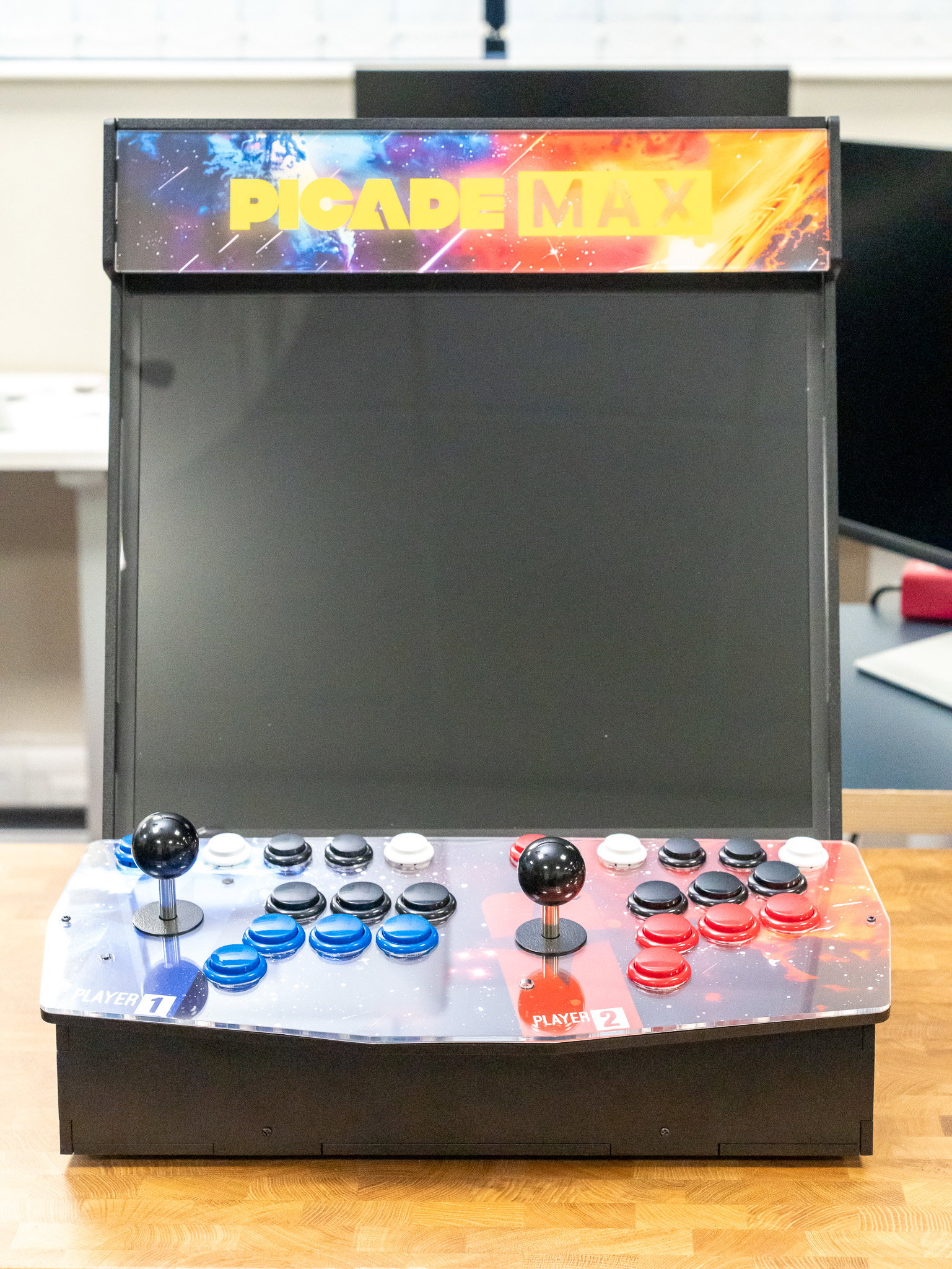
 Intermediate
Assembling Picade Max
Learn how to assemble and set up Picade Max!
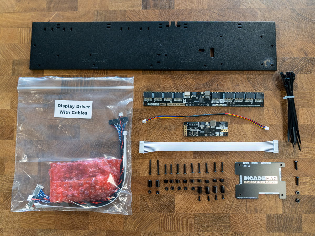
Time to add some smarts! For this step you'll need:
- Panel K
- The bag containing the display driver boards and associated cables.
- Picade Max USB Controller board
- Qw/ST cable
- Picade Max USB Audio board
- 9 pin JST-PH cable
- A bundle of cable ties
- Display driver cover
- 2x M2.5 22mm screws (longest)
- 9x M2.5 14mm screws (flat headed)
- 4x M2.5 6mm screws (shortest)
- 7x M2.5 nuts
- 9x M2.5 4mm standoffs (shortest)
- 6x M2.5 10mm standoffs (medium)
- 2x M3 12mm screws (shortest)
- 2x M3 nuts
Prepping panel K
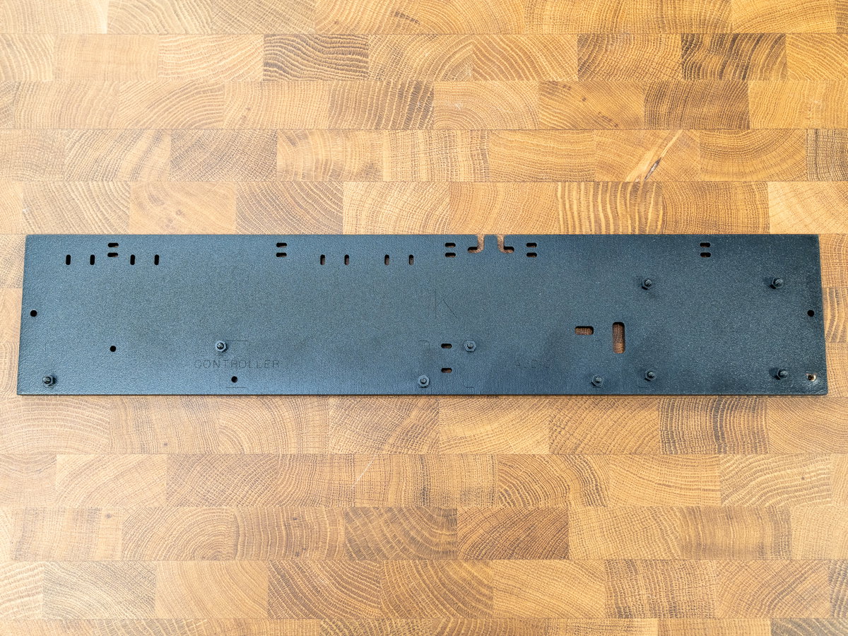
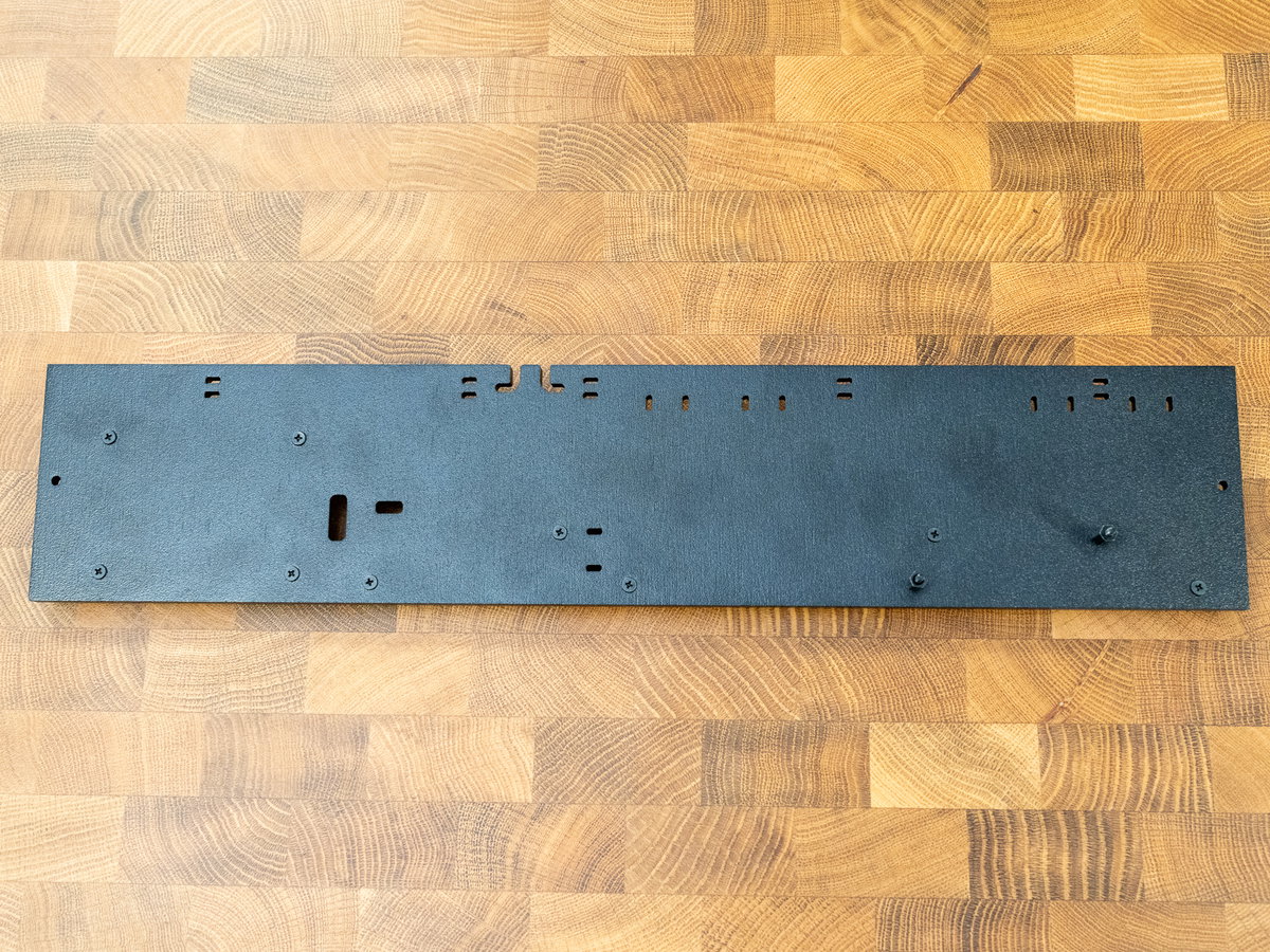
Panel K is the one that we're going to attach all the driver boards so first we'll need to install a bunch of bolts and standoffs to use as mounting points. Position the panel with the cable cutouts at the top edge and the big K facing you.
Thread the 9 flat headed M2.5 14mm screws through panel K, so the threads are pointing out of the side of the panel with the labels on. Then screw the 9 M2.5 4mm short standoffs onto the screw threads.
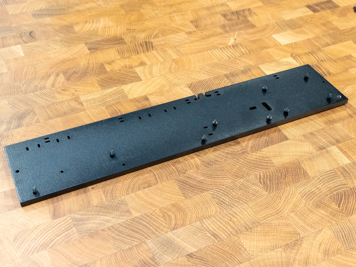
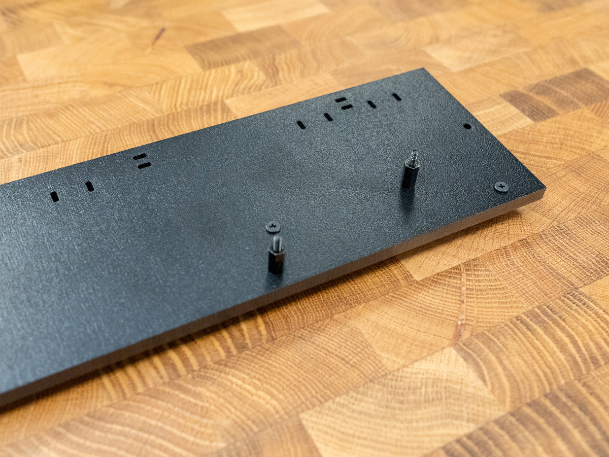
Flip the panel over, and poke the two long M2.5 22mm screws through the remaining two holes, so that the screw threads are pointing out of the non-label side. Add two M.2.5 10mm medium standoffs to secure them in place.
Mounting the smaller display driver board
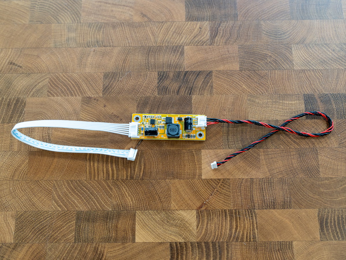
Open the 'Display Driver board' bag and locate the smaller display driver board - this one provides the screen backlight. Attach the white cable and the red and black cable to the appropriate connectors as shown.
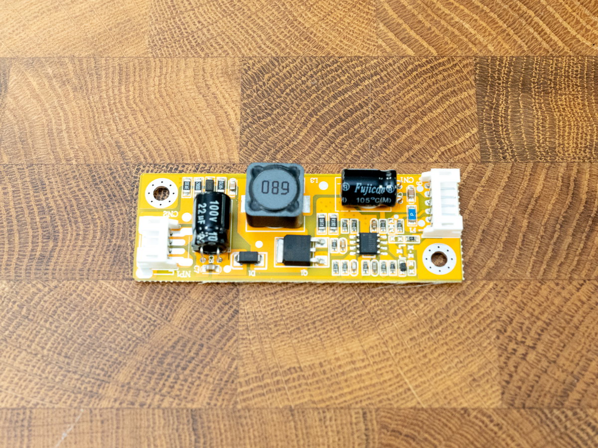
Mount the board onto the two screws on the non label side of panel K. The components on this board should be on the underside.
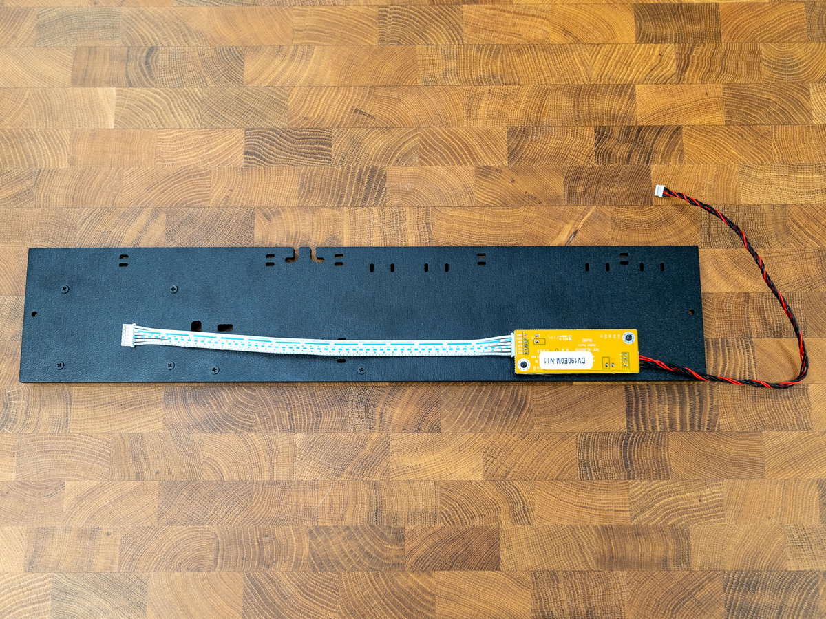
Then add two M2.5 nuts to secure it in place.
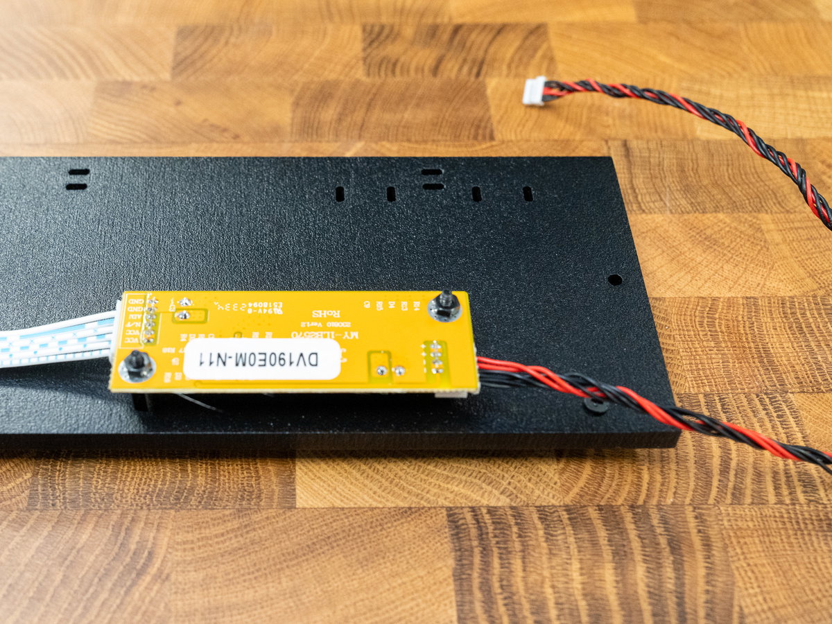
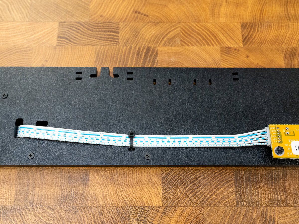
The white cable should thread through the slot in the panel. We added a cable tie to keep it in place.
Mounting the USB Controller board
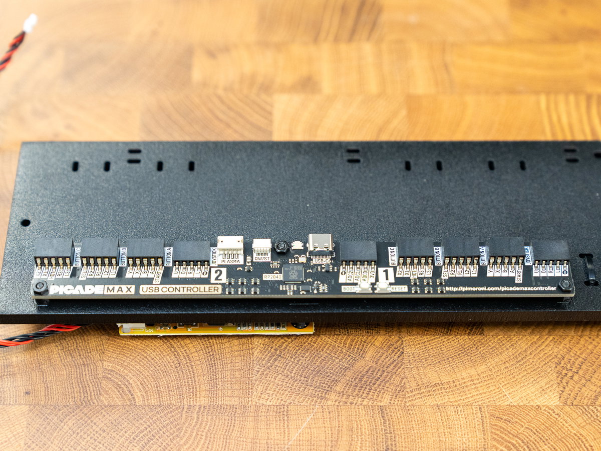
Flip panel K over again. We're mounting the Picade Max USB Controller board next, there are some markings on the panel to show you where it should go. Secure with three M2.5 nuts.
Mounting the USB Audio board
Next we're mounting the Picade Max USB Audio board (the speaker connectors should be on the top side, and the text should go the same way up as the text on the controller board).
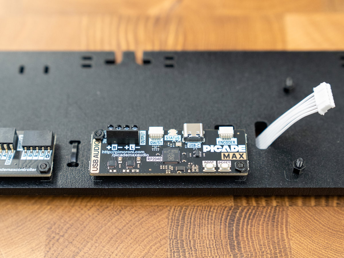
Fix it in place with two M2.5 nuts.
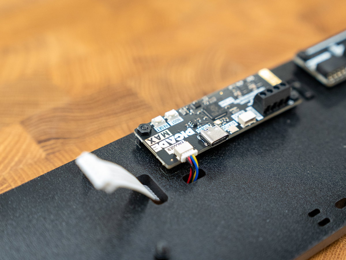
You can also plug in the 4 pin Qw/ST cable now - this will eventually connect the USB Audio board to the Encoder volume control. Make sure you use the connector marked 'Encoder' on the USB Audio board. Once it's plugged in, you can thread the cable through the cutout in panel K to keep everything tidy.
Mounting the larger display driver board
Locate the other, larger display driver board. It plugs into the other end of the white cable.
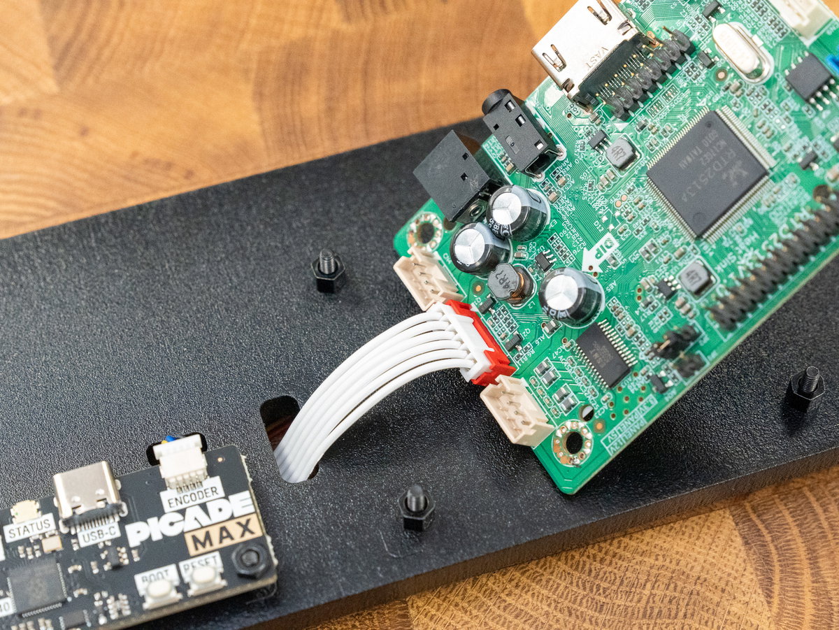
Place the display driver board over the remaining four screws. Then secure it in place with four M2.5 10mm medium standoffs.
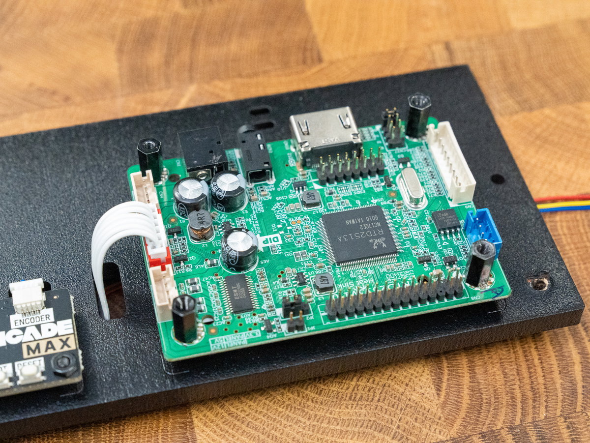
Plug one end of the 9 pin JST-PH cable into the connector into the 9 pin connector on the display driver board.
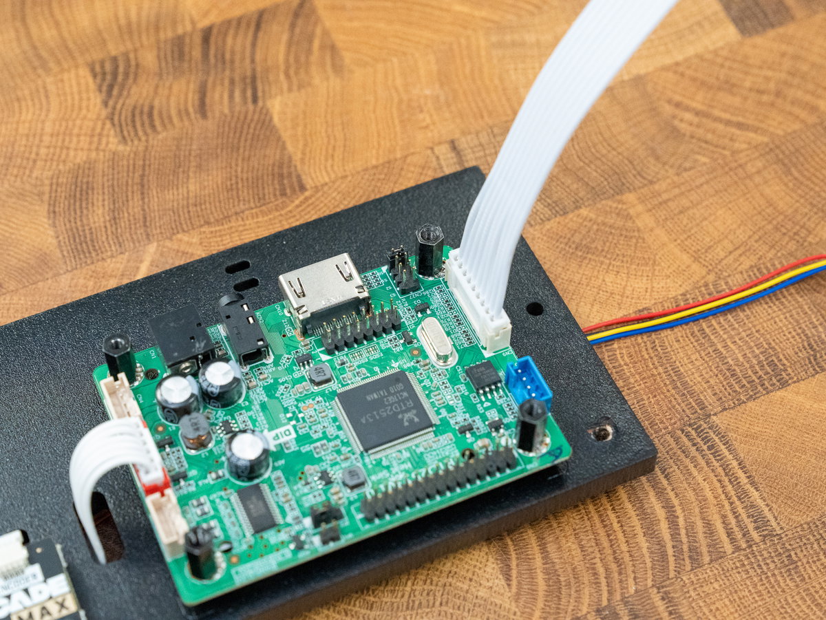
Next we're plugging in the cable with the red, black and blue wires - this is the cable which will eventually connect to the display panel. The 2x15 connector is not keyed, so make sure to double check that it is plugged into the driver board the correct way around. The end of the connector with the red power lines should be at the end of the board with the 9 pin JST-PH connector. There should also be a dot on the connector at the end of the cable that should be at the same end as the white dot on the board.
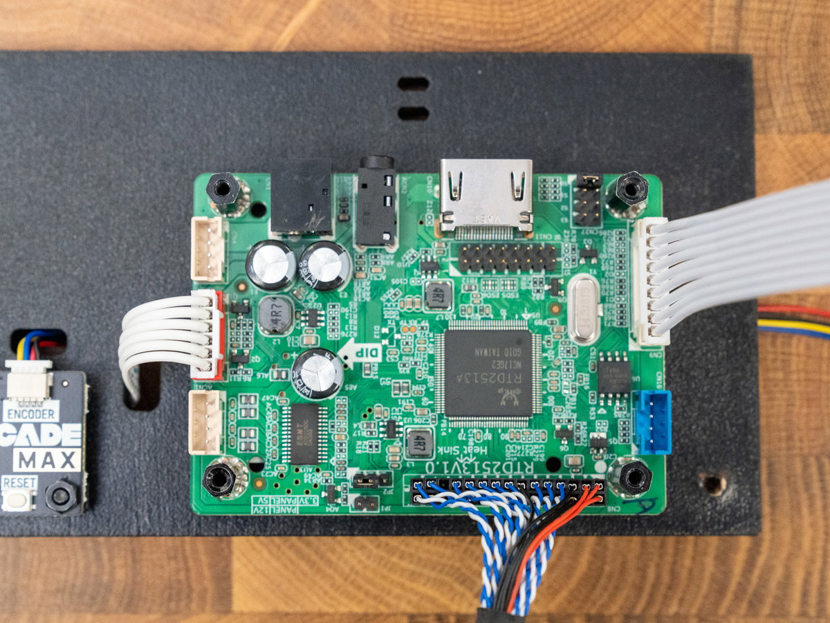
Use the 4 M2.5 6mm short screws to attach the display board cover - this protects the display driver board and keeps everything nice and neat.
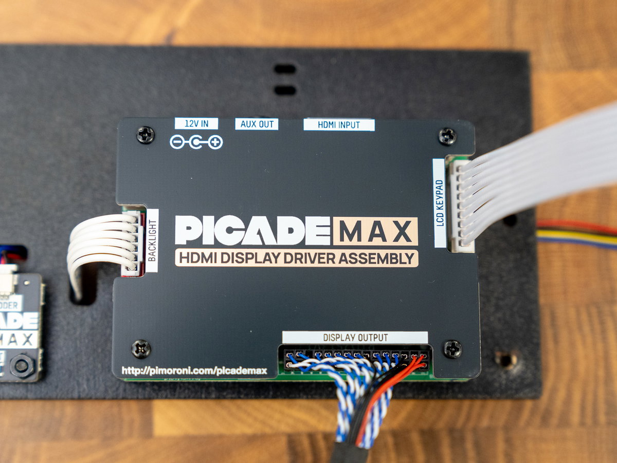
Once you've attached everything to it, your panel K should look something like this:
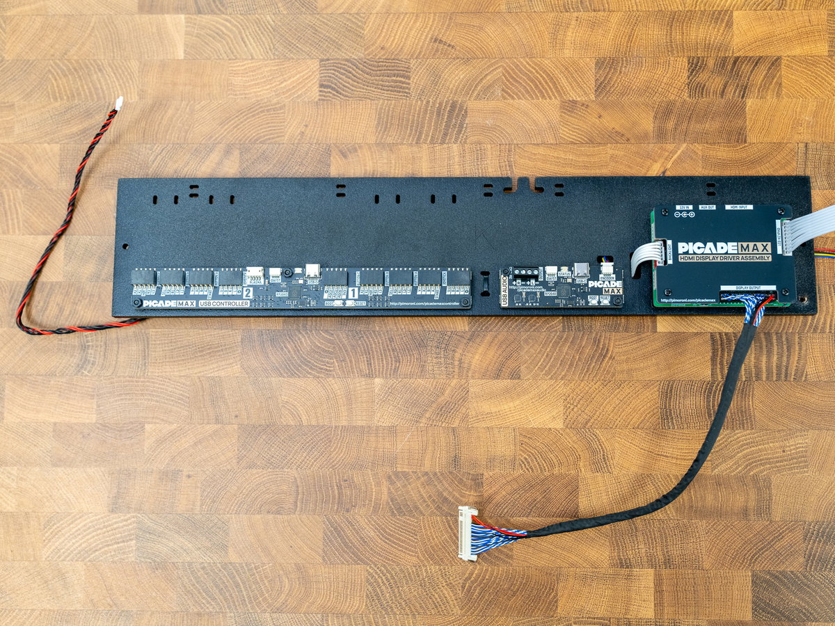
Attaching the speakers to the USB Audio board
Now is a good time to attach the speaker wires to the Picade Max Audio board. One by one, loosen the screw terminals and slot in the wires, matching red to + and black to -. Then tighten up the screws and give the wires a little tug to make sure they're securely anchored in the terminals.
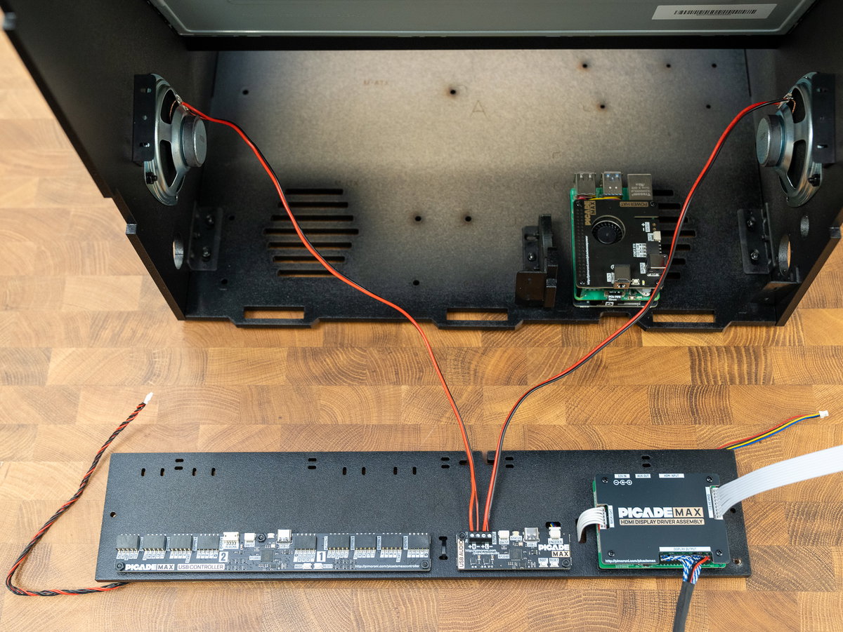
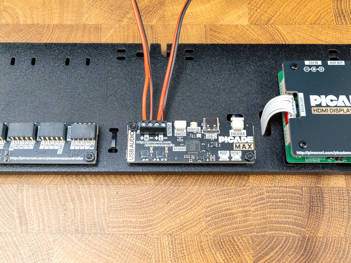
It's easier to tidy up the speaker wires now, before you attach this panel to the cabinet. Tuck the cables through the cutouts in panel K above the Audio board.
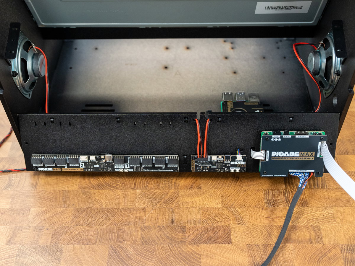
Flip the panel over and cable tie the wires to the rear of the panel.
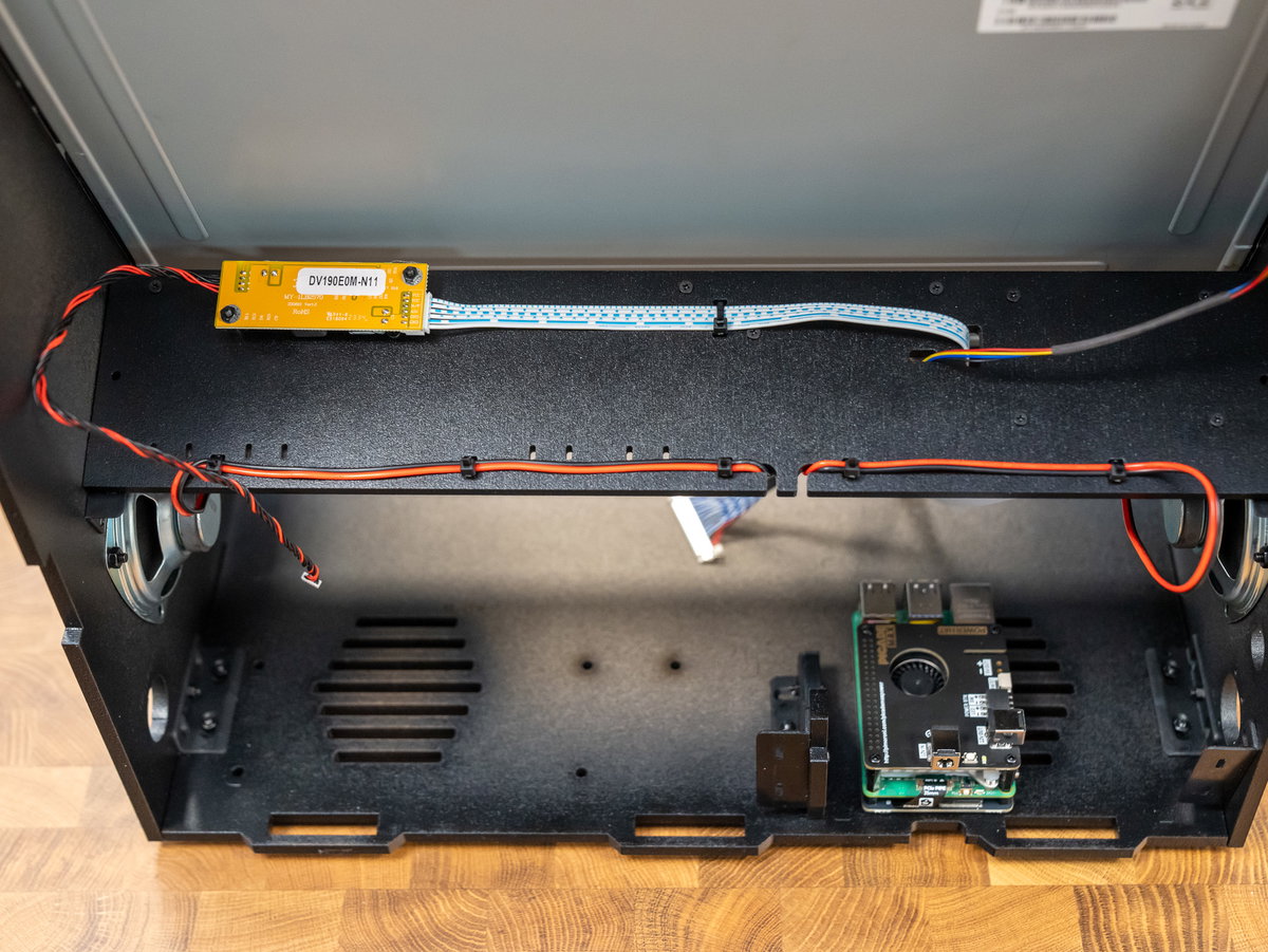
Turn panel K the right way up again and attach it to the brackets on the cabinet using 2 M3 12mm short screws and nuts.
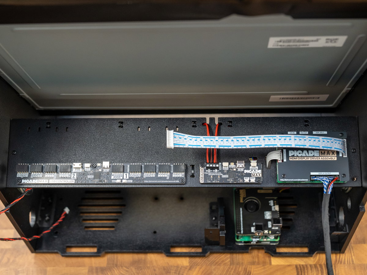
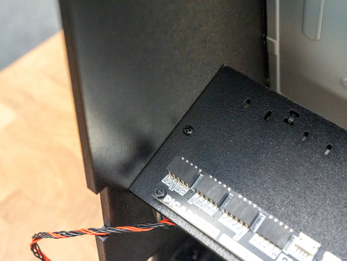
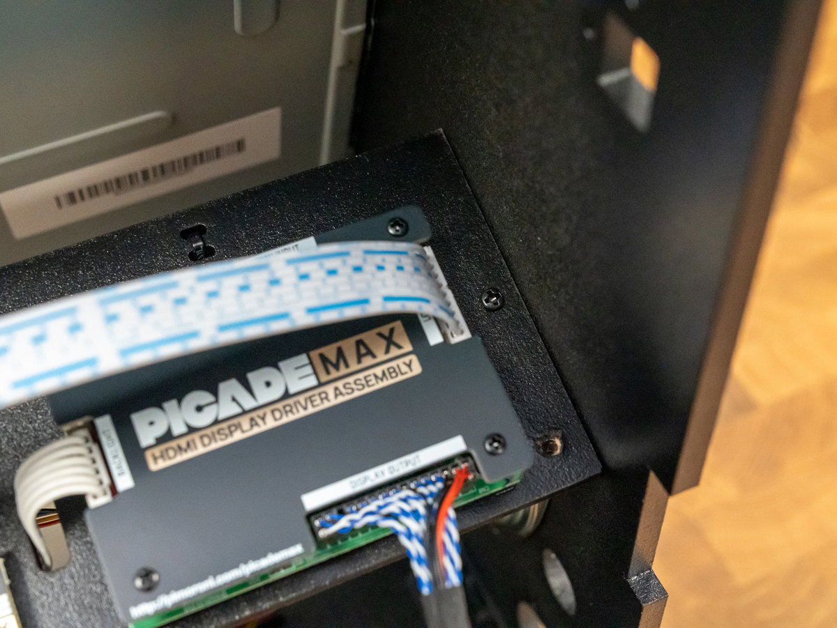
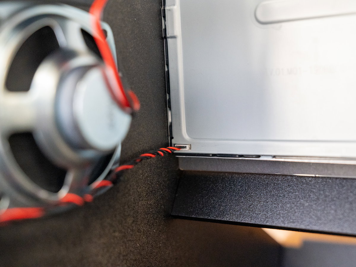
Plug the red and black wire from the smaller display driver board into the connector at the bottom left corner of the display panel.
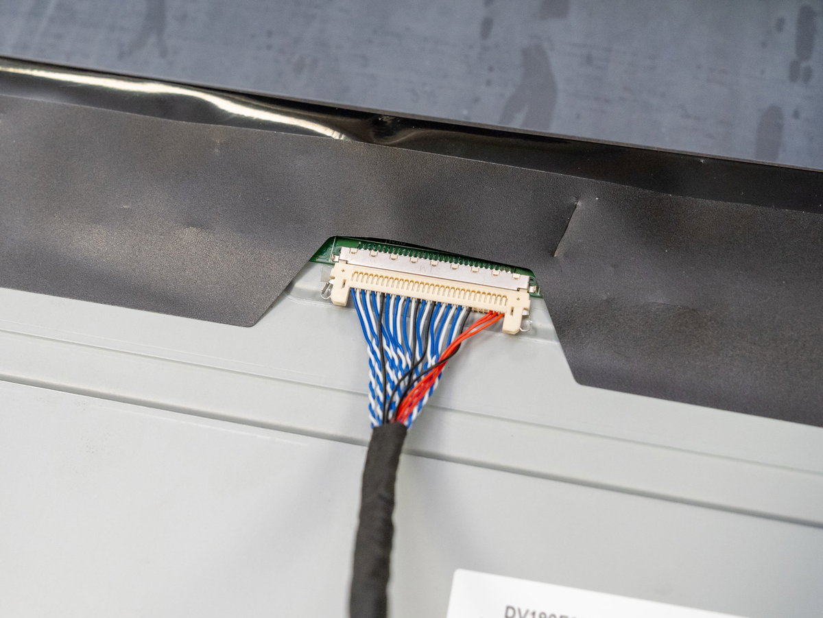
Then plug the red, black and blue cable from the larger display driver board into the connector at the top of the display panel. This connector will only go in one way round, with the red wires on the right hand side of the connector.
Adding the display controls, volume knob and power button
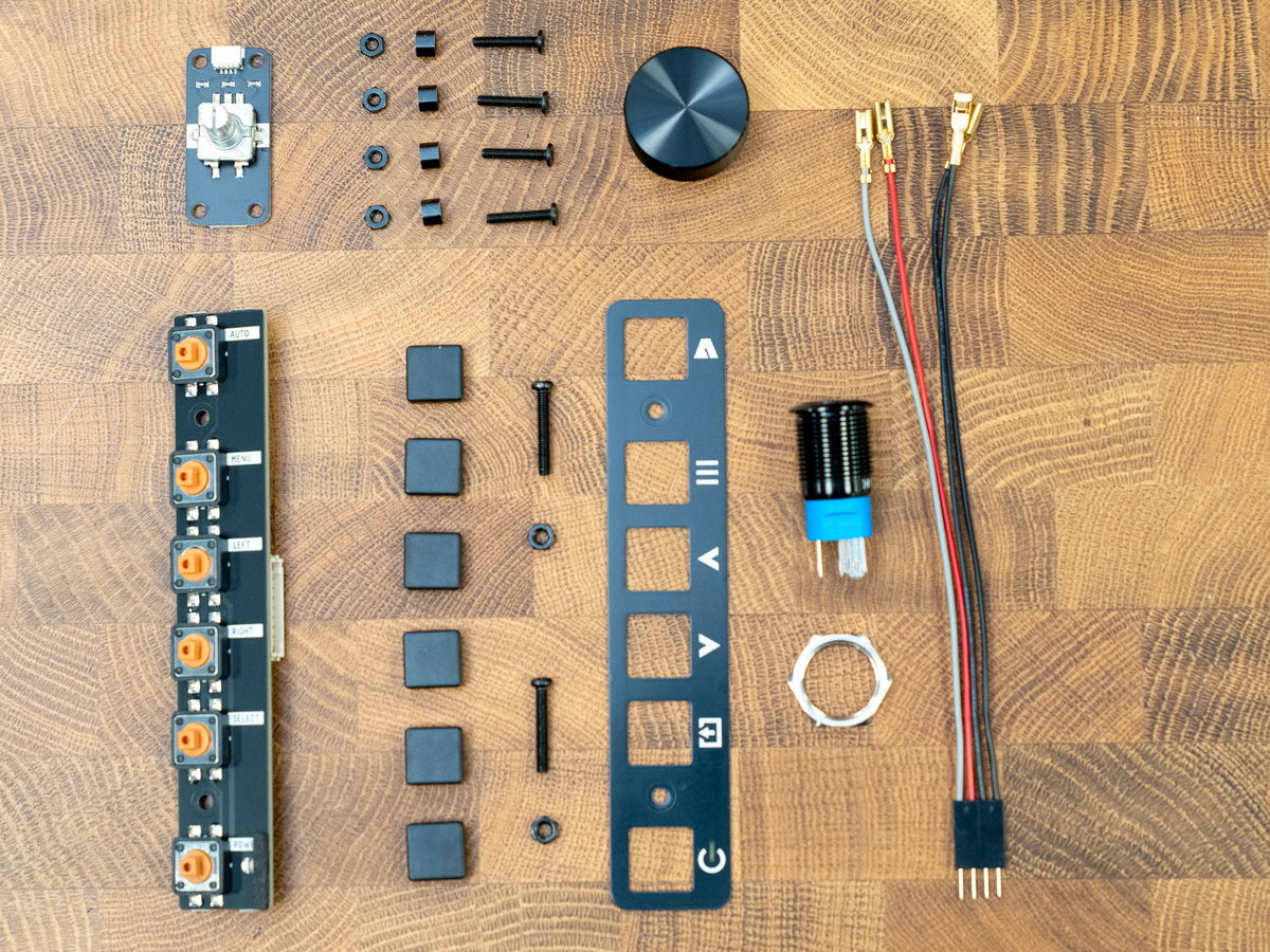
For this section you'll need:
- Volume knob
- Picade Max Encoder board
- Picade Max LCD Keypad board
- Picade Max Keypad Legend
- Square black keycaps for LCD Keypad
- 4x M2.5 14mm screws (flat headed)
- 4x M2.5 nuts
- 4x M2.5 4mm standoffs (short)
- 2x M3 x 18mm screws (long, find them in bag 2)
- 2x M3 nuts
- The illuminated power button
- 4x power button cables (from the wiring loom)
Fitting the volume dial
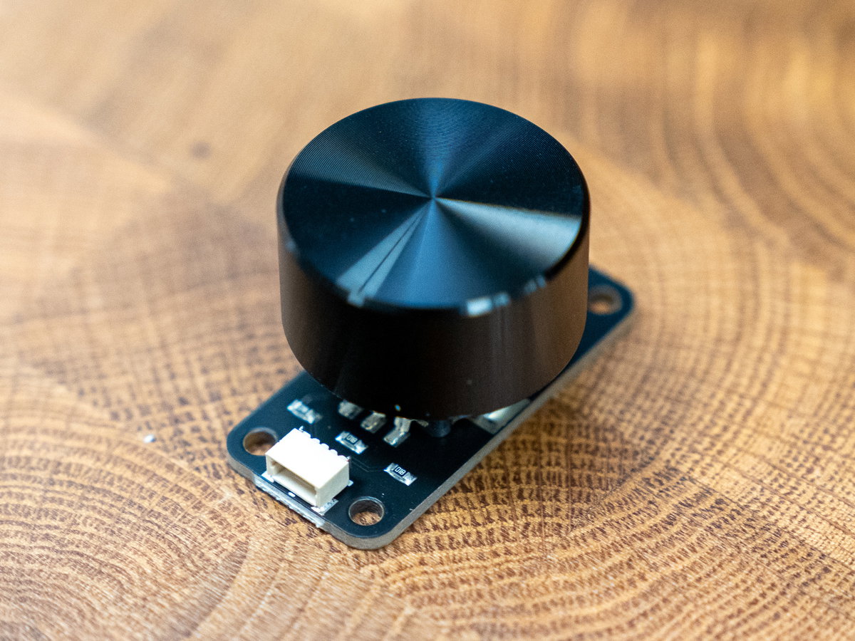
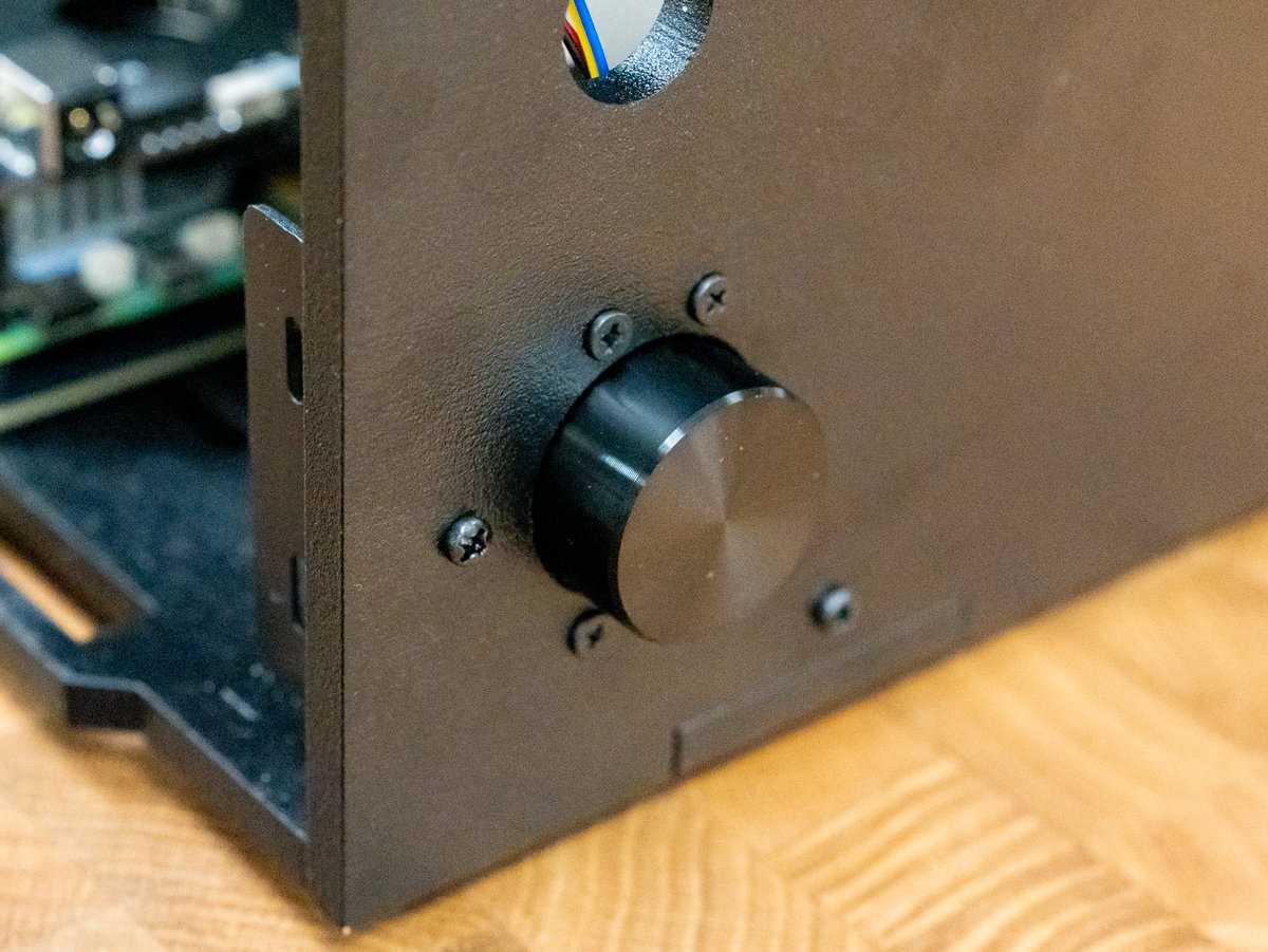
Attach the dial to the encoder board (it just pushes onto the shaft of the encoder).
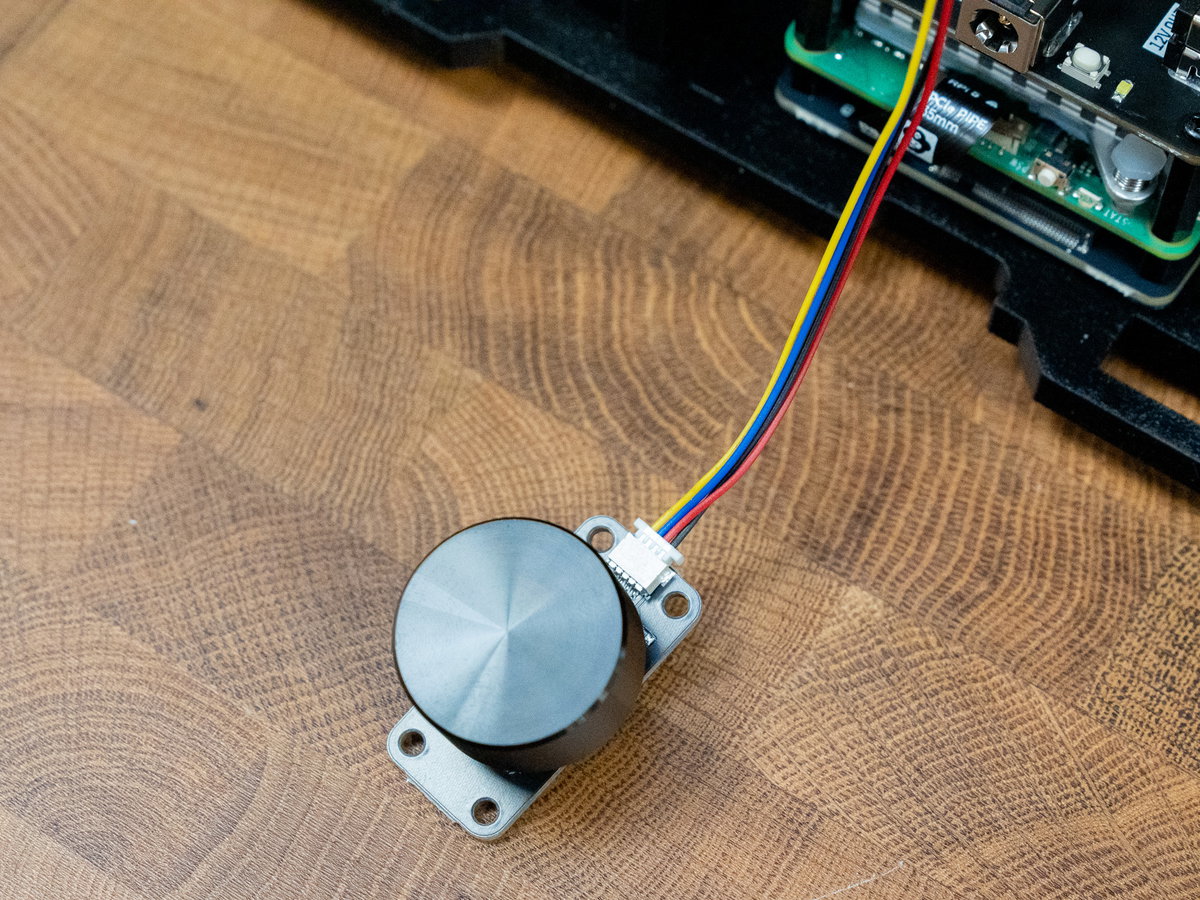
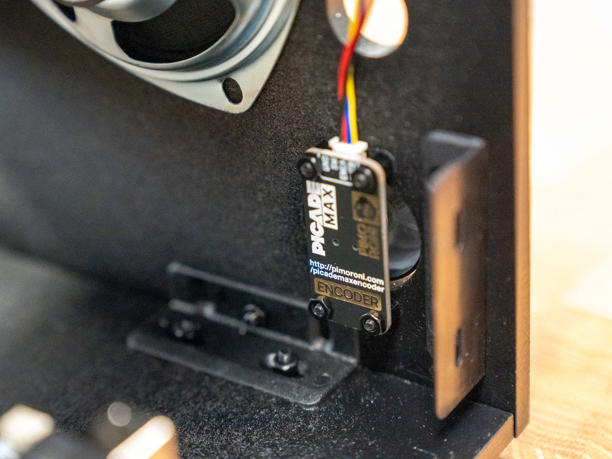
Plug the end of the 4 pin Qw/ST cable (from the USB Audio board) into the encoder board.
Poke the 4 M2.5 14mm flat headed screws through the holes surrounding the larger hole in panel E, from the outside of the cabinet.
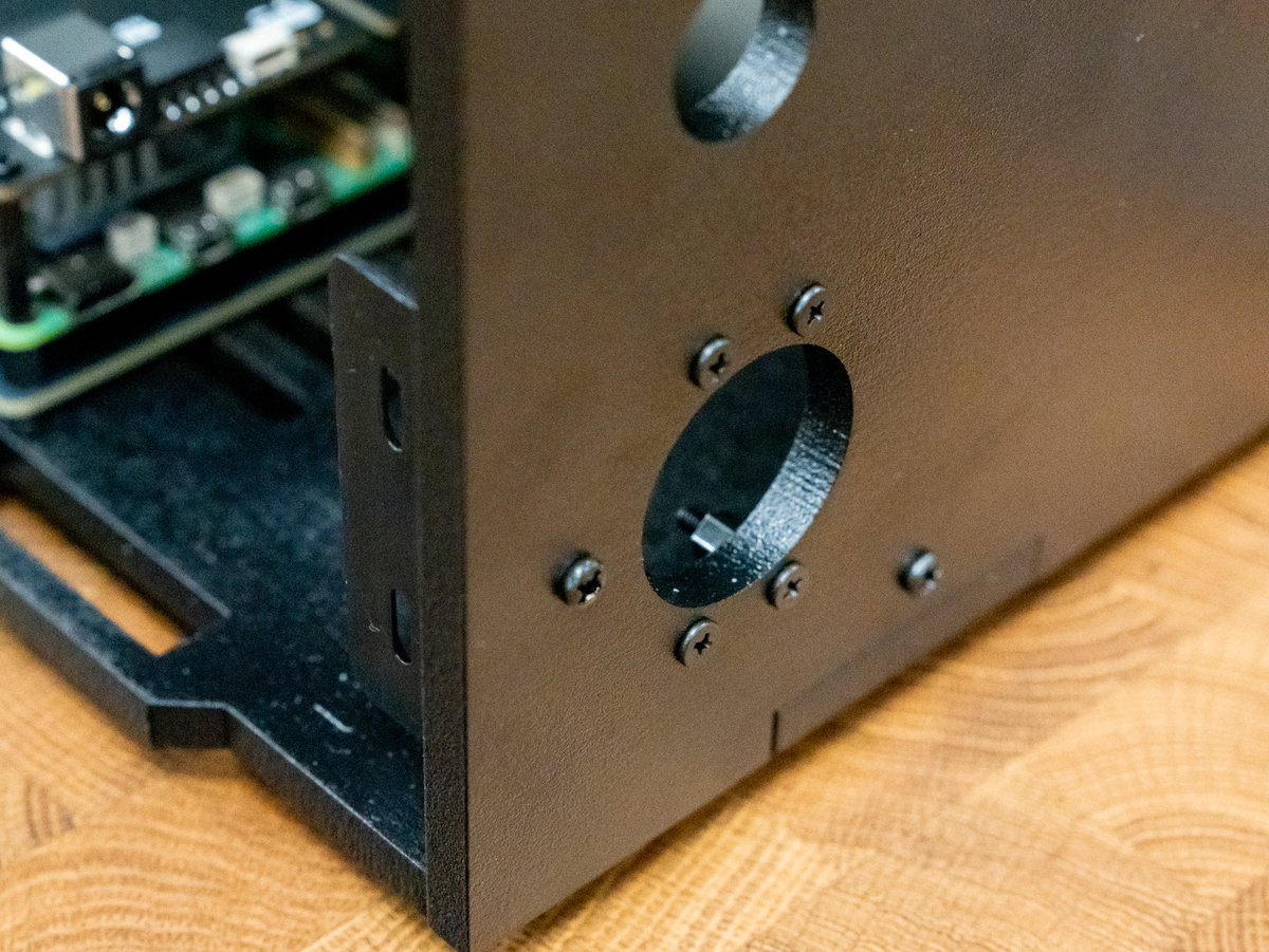
Screw on the M2.5 4mm short standoffs (inside the cabinet).
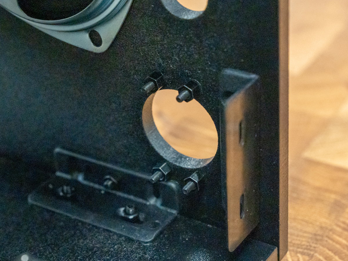
Then slot the encoder assembly through the hole from the inside of the cabinet, so that the screw threads pass through the four mounting holes in the board and the dial goes through the big hole in the middle. We'd suggest positioning the cable so it points upwards out of the top edge of the encoder board. Fasten everything in place with four M2.5 nuts.
Fitting the power button
Unscrew the metal hex ring from the power button if you haven't already, and take a look at the contacts on the underside of the button. There are five contacts, but we'll only be connecting wires to four of them.
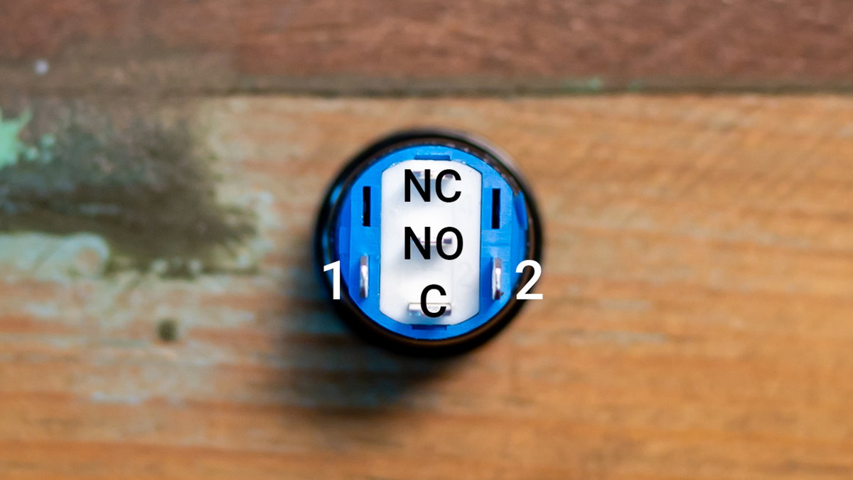
First we'll connect up the LED part of the button. Push the spade connectors on the red and grey wires onto contacts 1 and 2 (the ones sticking out of the blue bit), either way round.
Then we'll connect up the switch part. Push the spade connectors on the two black wires onto the contacts labelled C and NO (they're the two contacts between the wires that you just plugged in).
Check that none of the metal connectors plugged into the back of the button are touching each other, you can gently bend the contacts slightly to separate them if they are.
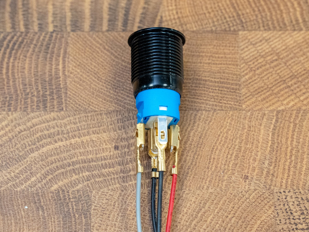
Thread all the wires and the button through the smaller hole in panel E, from the outside.
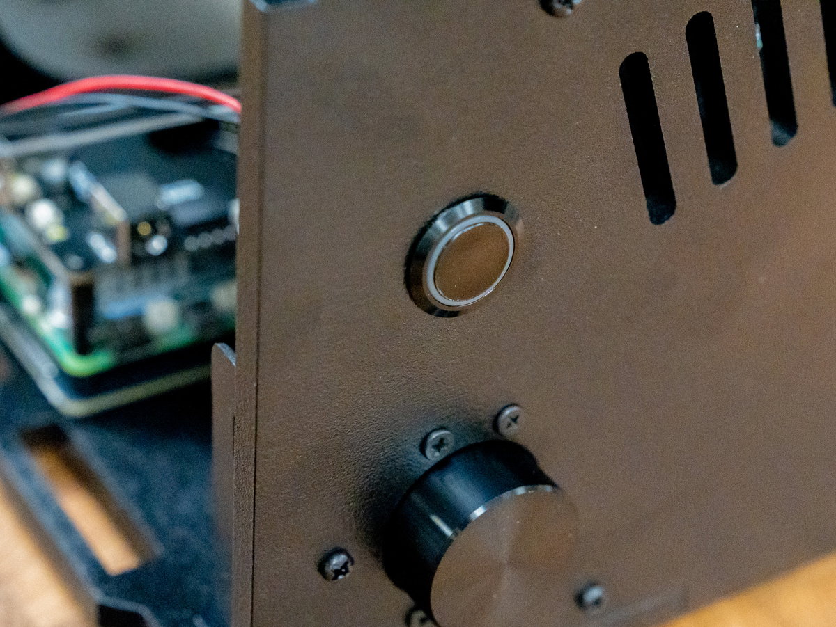
Then attach the metal hex ring to the inside of your Picade to hold the button in place.

Now you can plug the other ends of the wires into the Picade Max Power HAT. The DuPont connectors on the black wires should slot onto the SW (switch) pins on the HAT (polarity doesn't matter). The connectors on the red and grey wires should go to LED (polarity also doesn't matter here, assuming you're using our button).
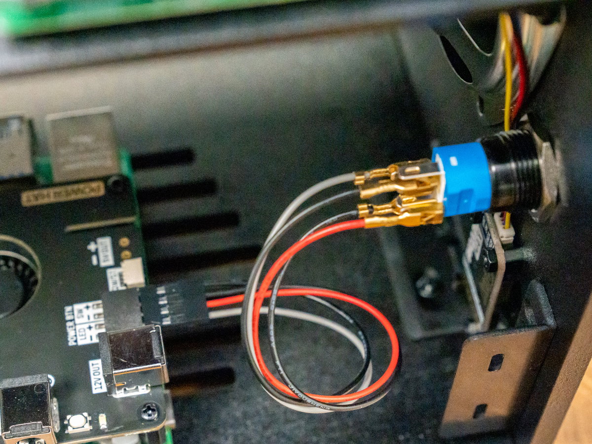
Ta da! The volume dial and power button should both now be safely plumbed in.
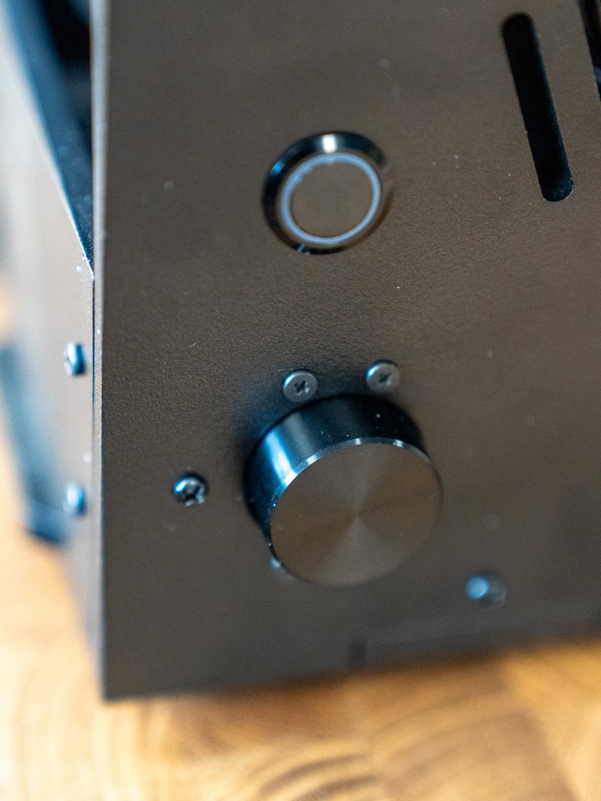
Fitting the LCD controls and legend
Add the square black keycaps to the Picade Max LCD Keypad board (they should just push on to the switches, but they do require quite a bit of pressure).
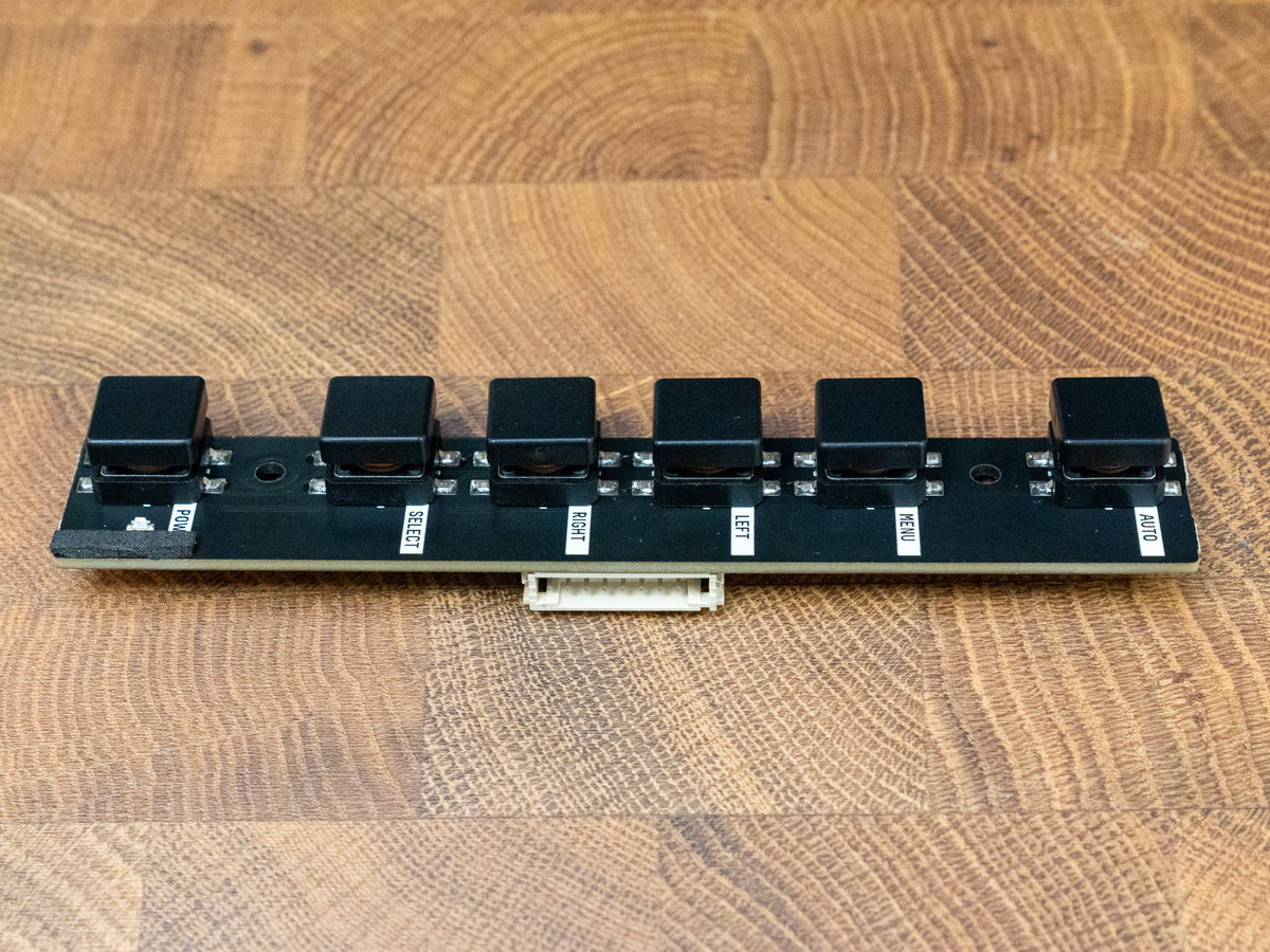
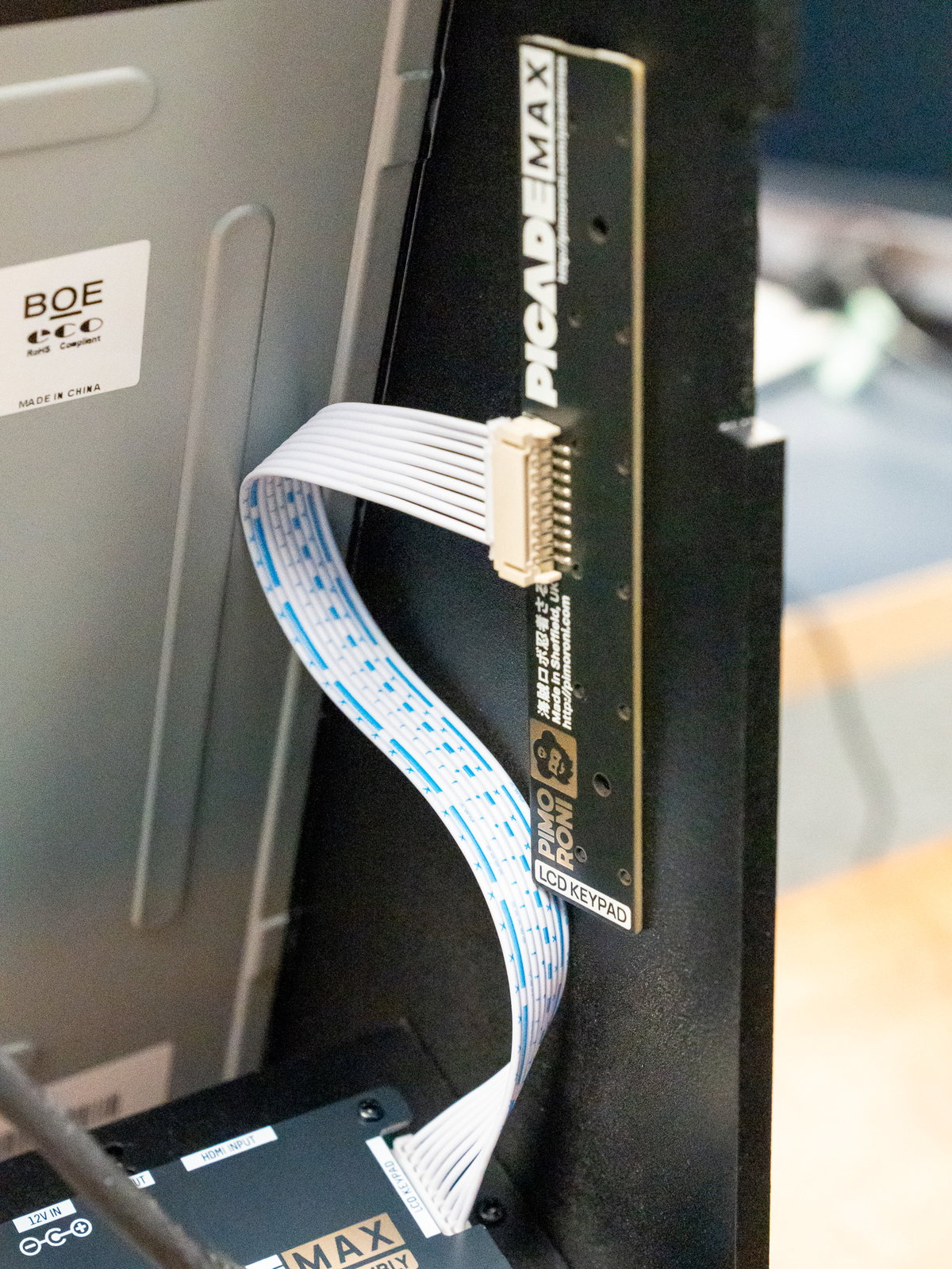
Plug the end of the 9 pin cable (from the display driver board) into the connector on the LCD Keypad board (it will only go in one way).
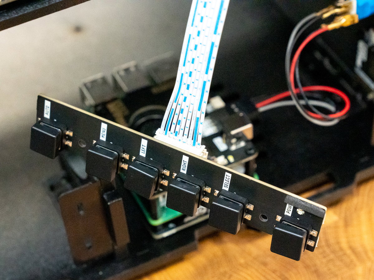
Slot the buttons on the keypad through the holes in the side of the cabinet.
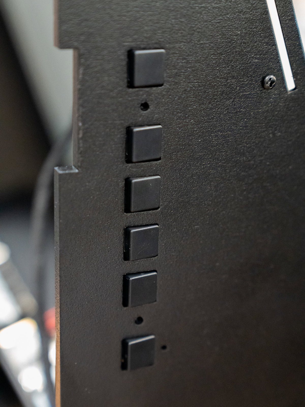
Place the keypad legend over the top of the buttons.
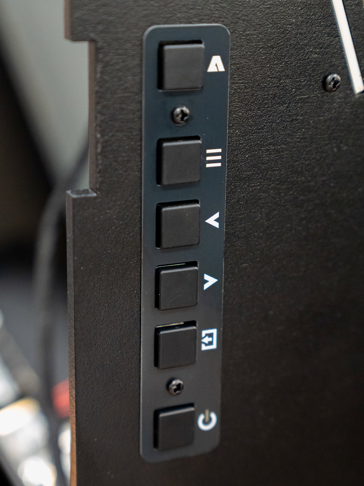
Then fasten the keypad and legend to the cabinet with the M3 18mm screws and nuts.
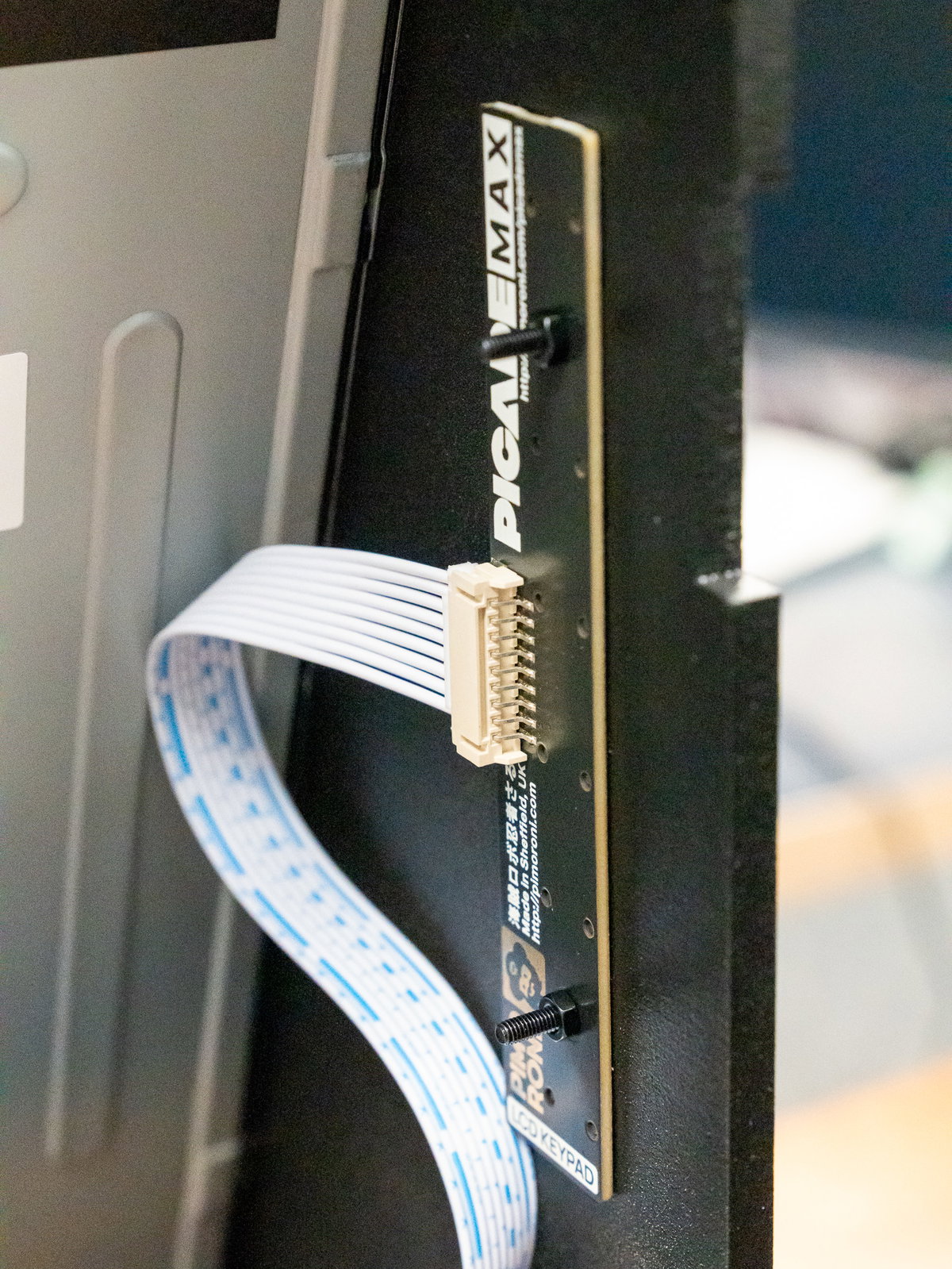
Part 3 is complete! Here's what things should look like:
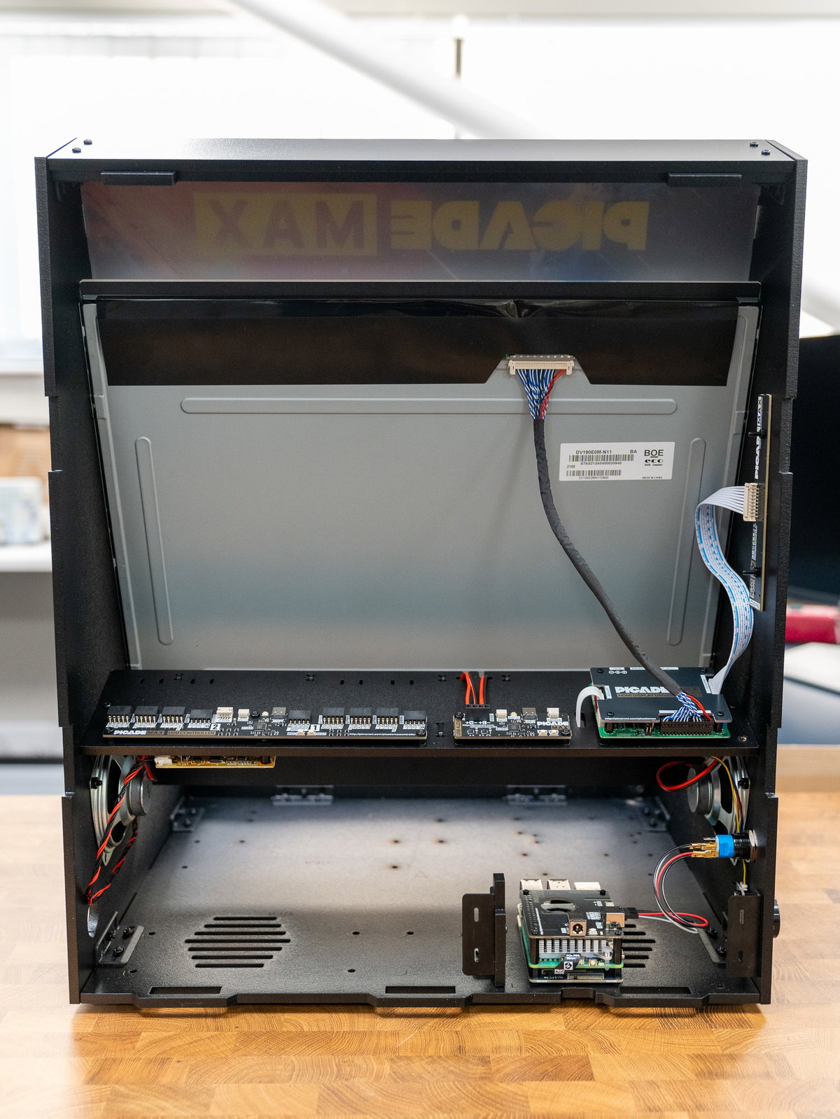
Give yourself a pat on the back, stretch and hydrate and when you're ready, progress to part 4.