 Intermediate
Assembling Picade Max
Learn how to assemble and set up Picade Max!
Plugging in the cables
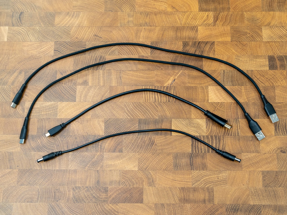
For this section you'll need:
- 2x 50cm USB A to C cables for connecting the Audio and Controller boards
- 30cm barrel jack to barrel jack cable for connecting the Power HAT to the display driver board
- 30cm micro HDMI to HDMI cable for connecting the Pi to the display driver board
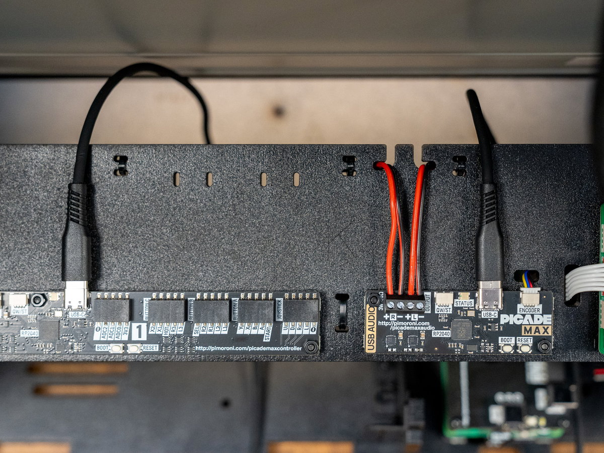
Plugging in the USB cables
Plug the USB-C ends of the USB A to C cables into the USB-C connectors on the Picade Max USB Controller and USB Audio boards.
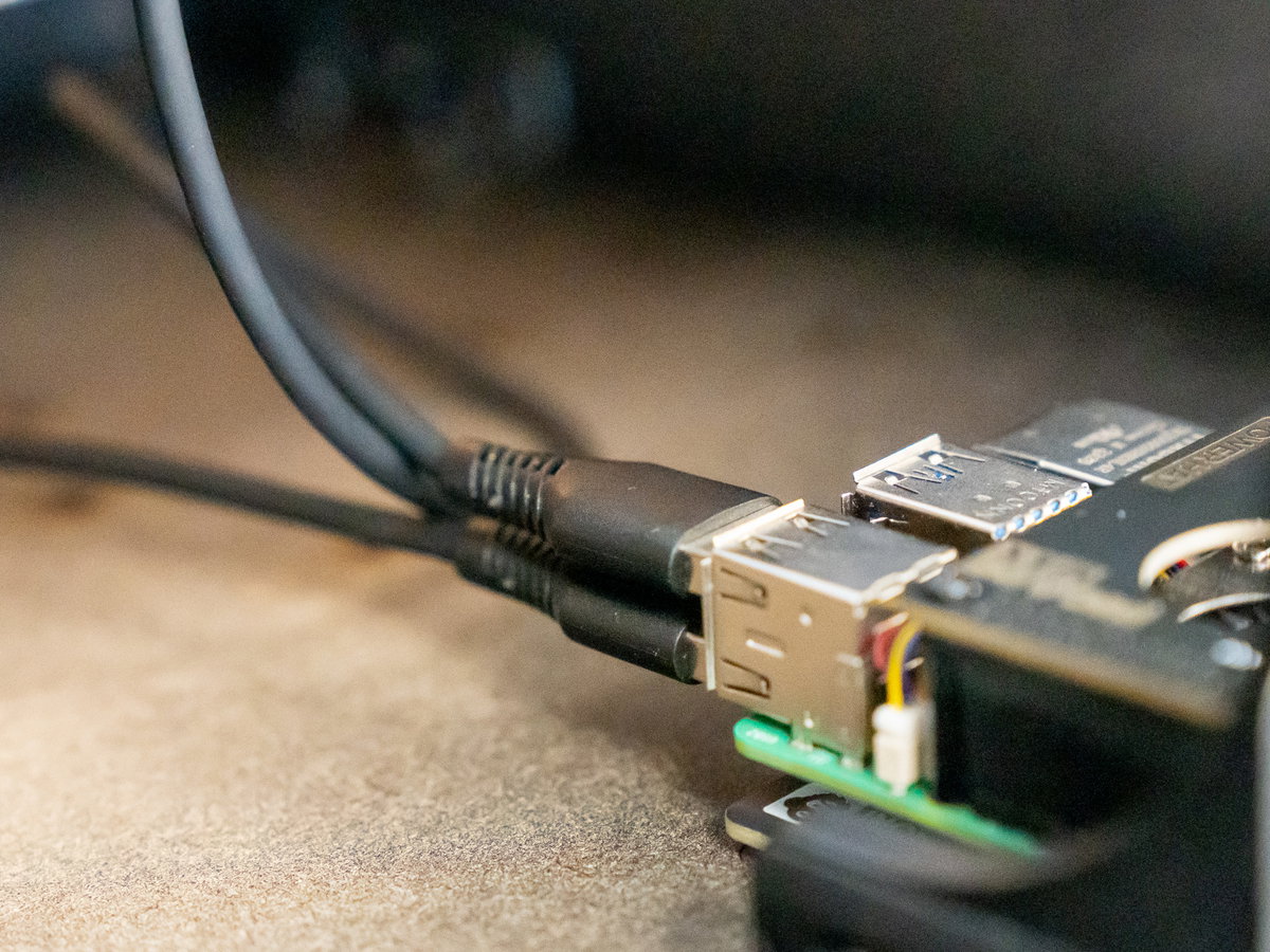
Then plug the USB-A ends into your Pi's USB ports.
Plugging in the HDMI cable and display power cable
Plug the big end of the HDMI cable into the connector marked HDMI INPUT on the display driver board. While you're here, you can also plug one end of the barrel jack cable into the connector marked 12V IN.
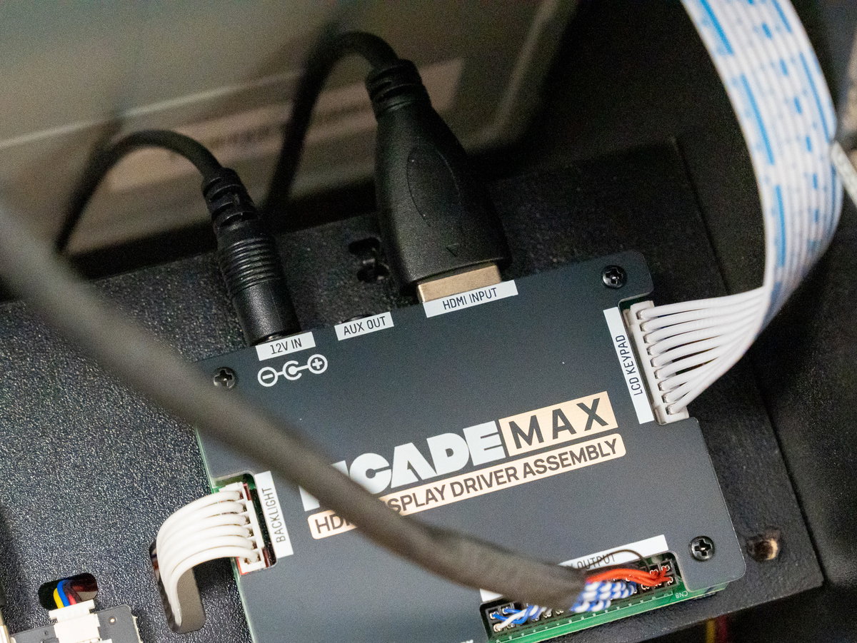
Then connect the small end of the HDMI cable to one of the micro-HDMI ports on your Pi (we'd suggest using HDMI-0 as it's the default display in Raspberry Pi OS - that's the one nearest the USB-C power input).
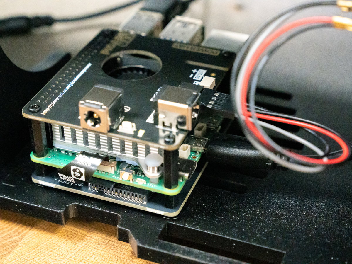
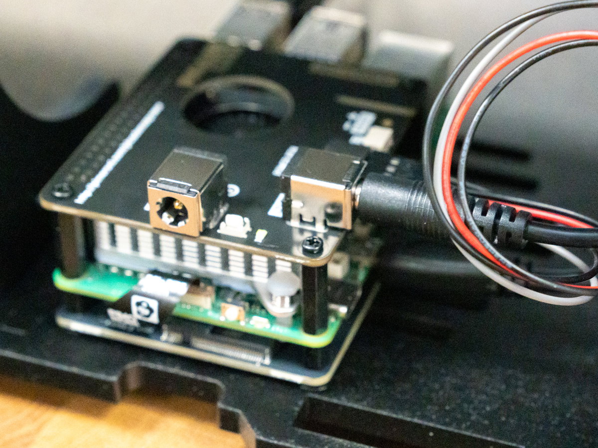
Plug the other end of the barrel jack cable into 12V OUT on the Picade Max Power HAT.
1UP or 2UP layout?
At this point of the build you'll need to decide whether you want to use the 1 player or 2 player layout. We'll be showing you the single player assembly steps first.
Console assembly (1 player)
Fitting the joysticks (1 player)
For this part you'll need:
- Wooden panel M (one player)
- 1x joystick
- 1x 5 pin joystick cable from the wiring loom
- 2x M4 12mm screws
- 2x M4 nuts
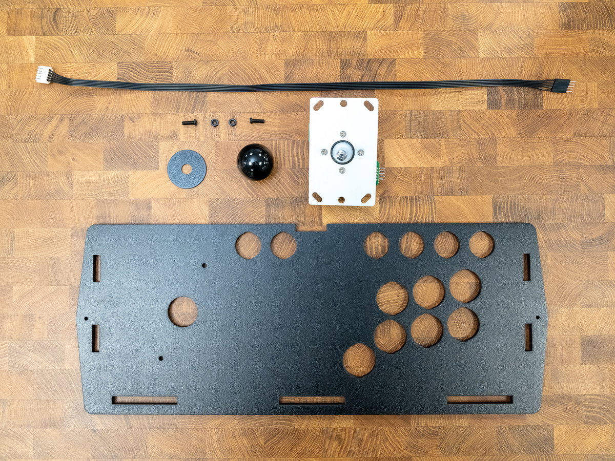
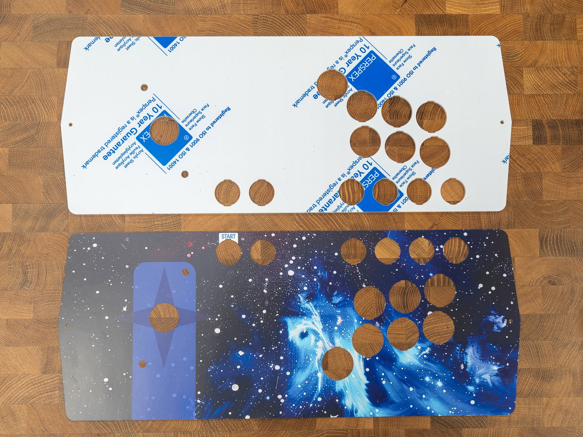
You'll also need the 1 player acrylic console panel and artwork.
Flip over the wooden panel so that the label side is facing you. There are some markings to show you where to position the joystick. If you're looking at the panel with the letter M the correct way up, the 5 pin connector should be pointing out of the left hand side of the joysticks.
Use the M4 screws and nuts to secure the joystick to the panel. Note that we're only using two of the four mounting holes.
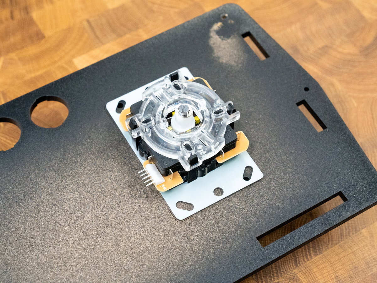
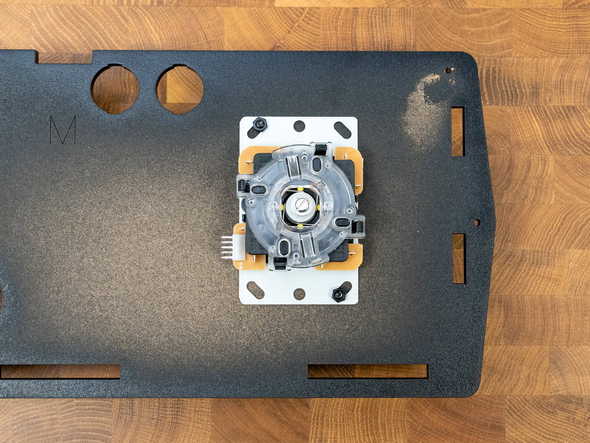
Tear off a 5 pin strip from the joystick cable. Use the chunky beige connector to attach the cables to the joysticks.
The 5 pin connectors on the joysticks are made of quite soft metal and can sometimes get a little squashed during transit. You might need to bend the pins slightly to straighten them out if you're having trouble plugging in the connector.
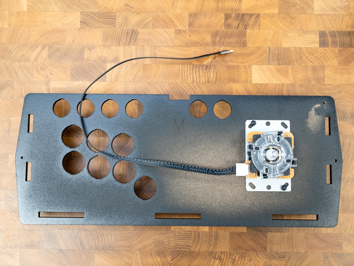
Position the console panel in front of the cabinet and poke the joystick cable into the cabinet from the front.
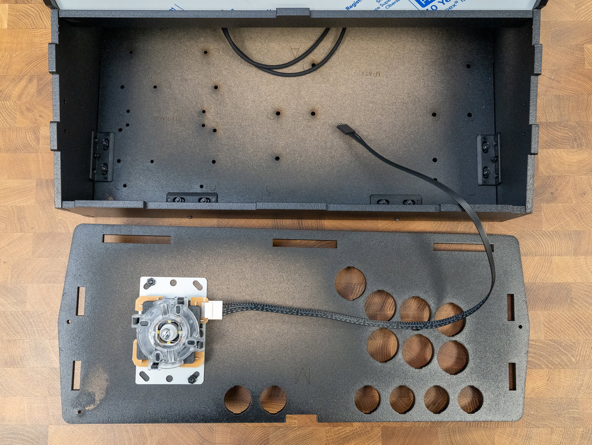
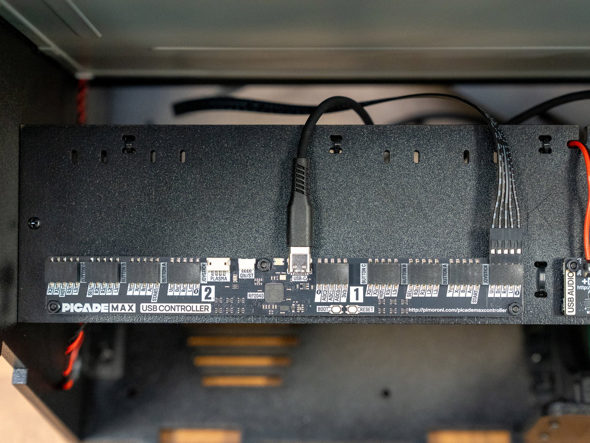
Feed the joystick cable up over the top of panel K and plug it into the player 1 connector on top of the Picade Max USB Controller board. The connector on the joystick cable has a little moulded arrow to show you where the ground wire is - match this up to the - marking on the board. You can also check that the printed grey markings on the joystick cable is facing towards you.
(If you find that only the 'up' direction is working on your joystick, you've probably got the connector orientation wrong - try unplugging the connector at the Picade Max USB Controller end, flipping it 180° and plugging it in again).
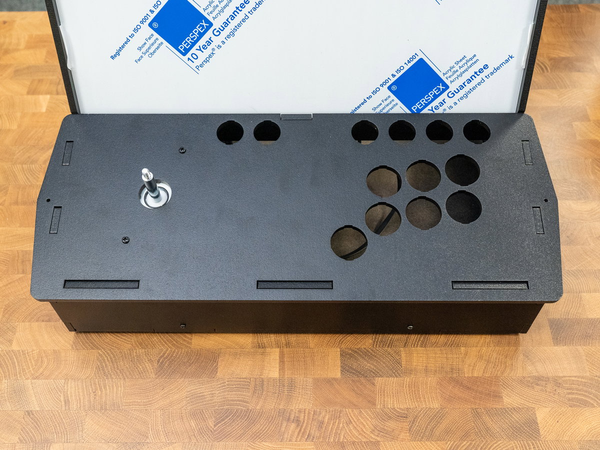
Now that the joystick is attached, flip the console assembly over and place it in its final position on the front of the Picade. We're not fastening it down yet though, you might find it useful to be able to flip it upside down whilst wiring up the buttons.
Next, place your cardboard console artwork on top of the console assembly, art side up and with the holes matching up.

Take your acrylic panel and identify the underside. Remove the protective coating from the underside of the acrylic.
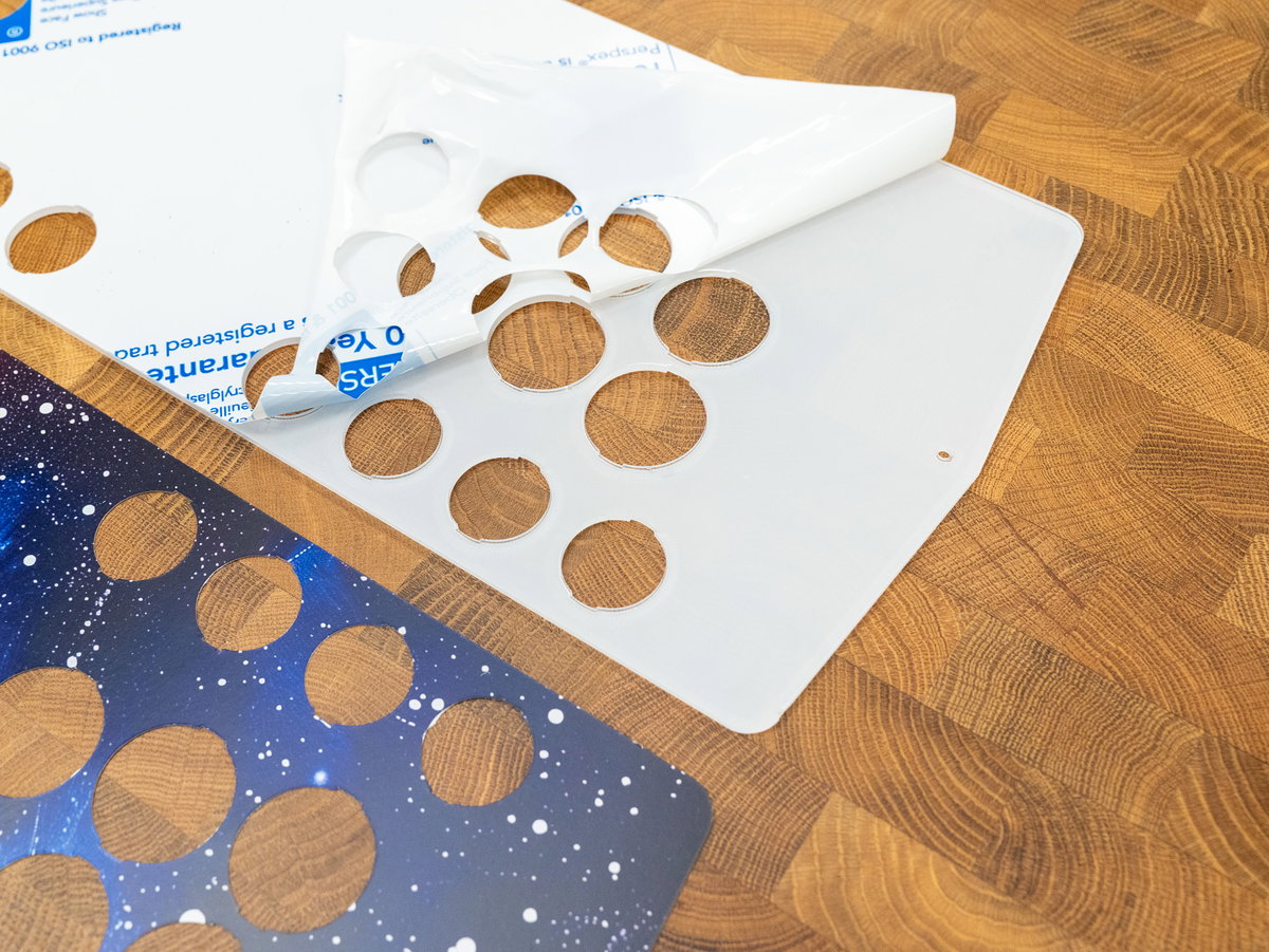
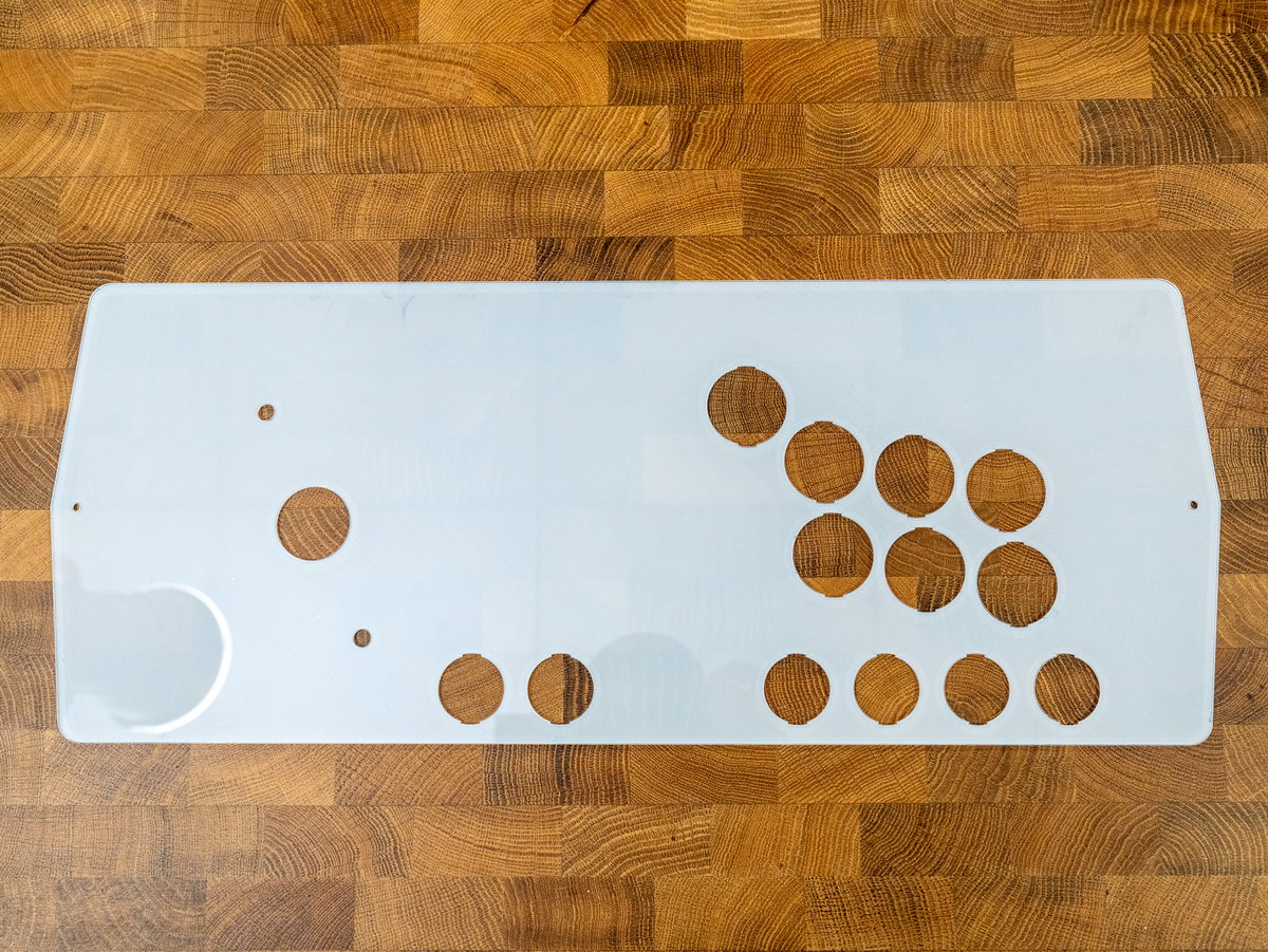
Then flip the acrylic piece over and place it on top of the console assembly, so that the freshly peeled side is touching the art.
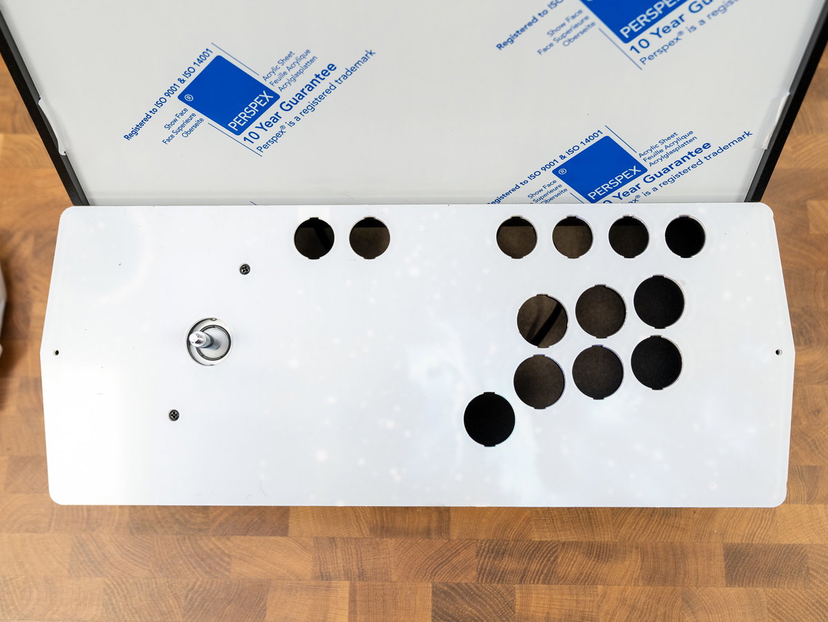
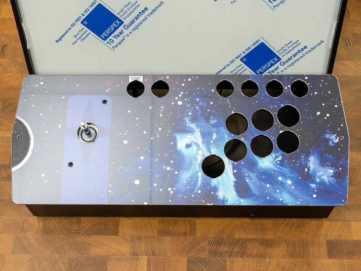
It's easiest to remove the protective layer from the top side of the acrylic now, though it is possible to leave it on until later if you want to. If you leave it until after you've fitted the buttons, you'll probably need to remove it in pieces.
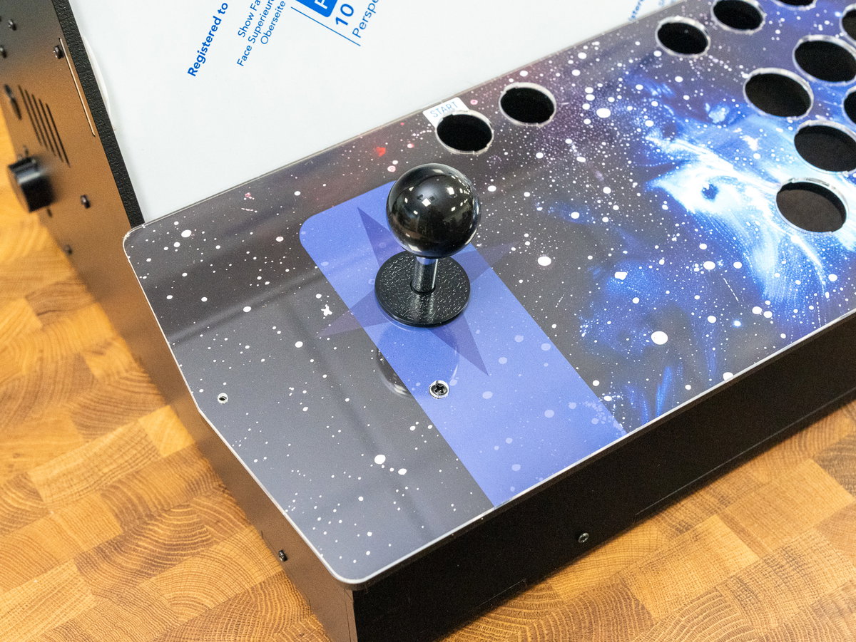
Add the collar and screw on the joystick ball.
Fitting the buttons (1 player)
For this section you'll need:
- The 24 and 30mm arcade buttons
- The DuPont pin to spade connectors cables (from the wiring loom)
If you're installing the 1 player console you'll need:
- 3x 30mm black button
- 4x 30mm blue button
- 3x 24mm black button
- 1x 24mm blue button
- 2x 24mm white button
- 14x DuPont pin to spade connectors cables (from the wiring loom)
- A 24mm button of your choice for the side cabinet button
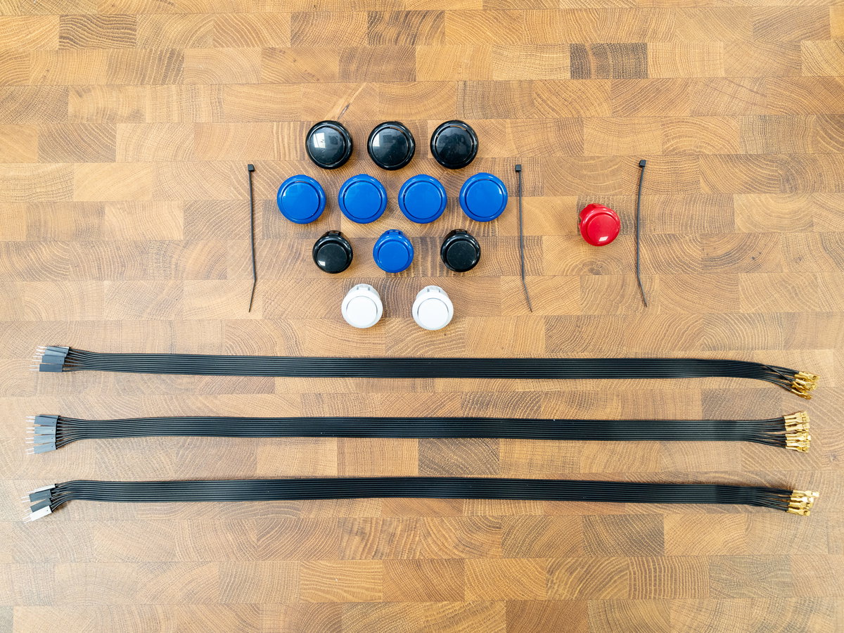
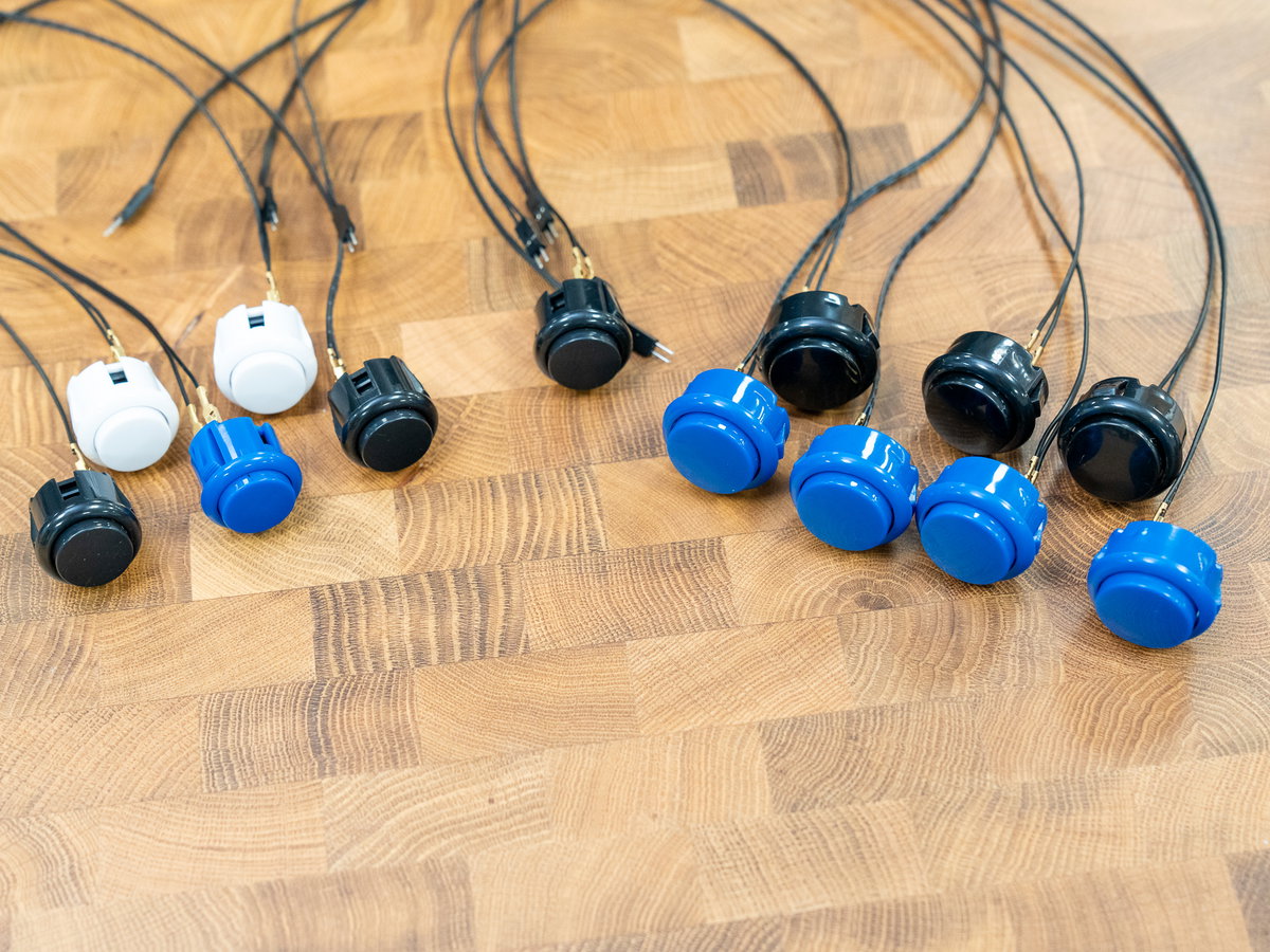
Separate the cables from the wiring loom into 14 pairs of wires - each pair should have two DuPont pin connectors on one end and two spade connectors on the other. Push the spade connectors onto the terminals on each button.
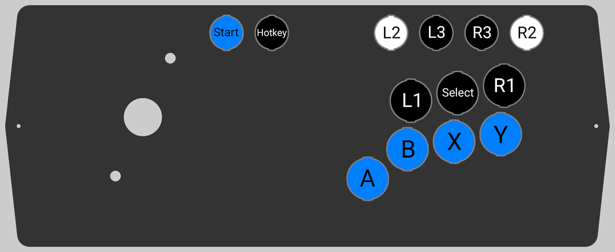
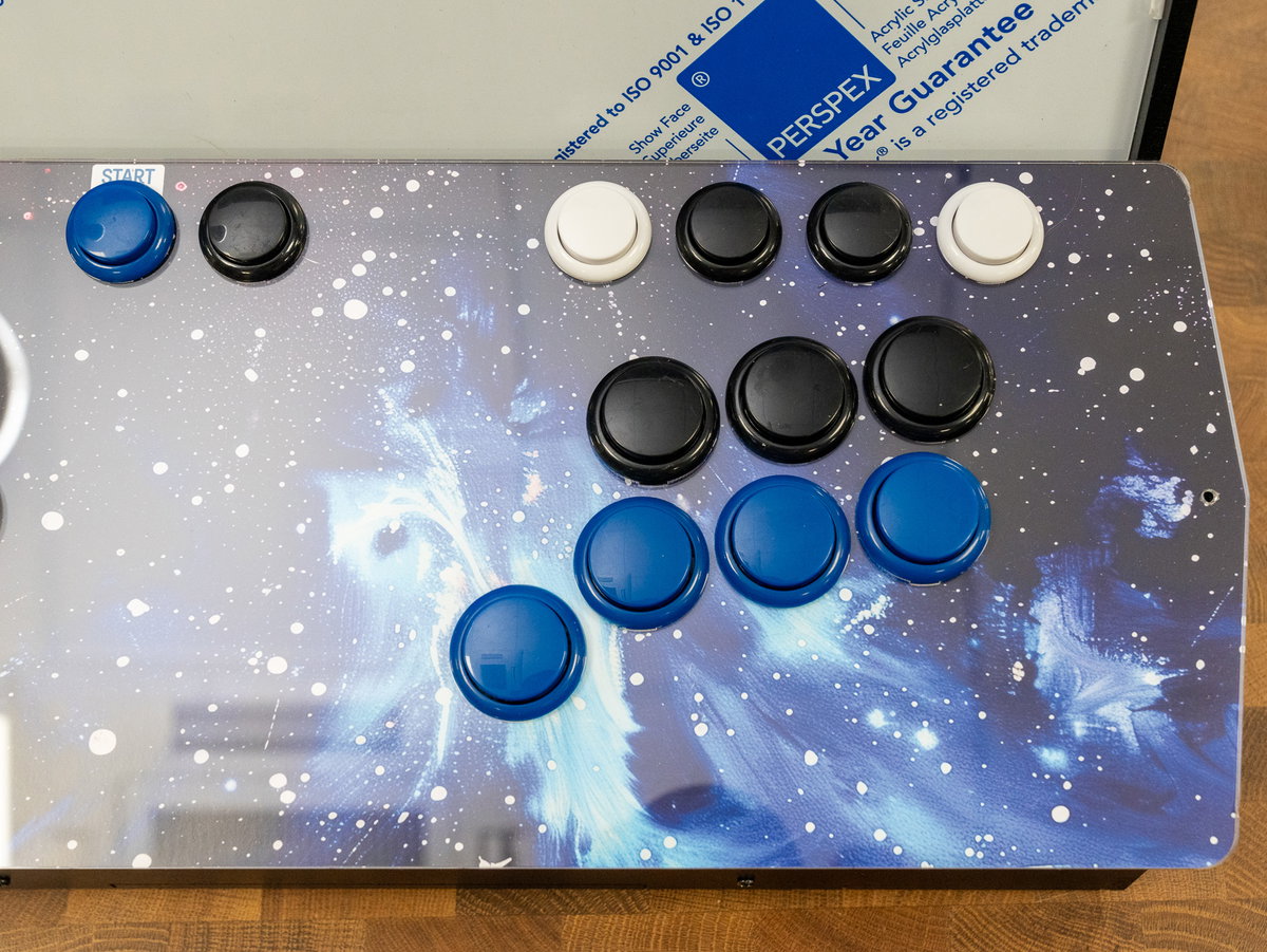
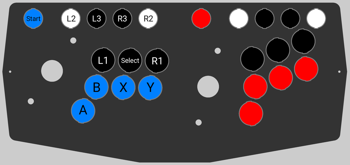
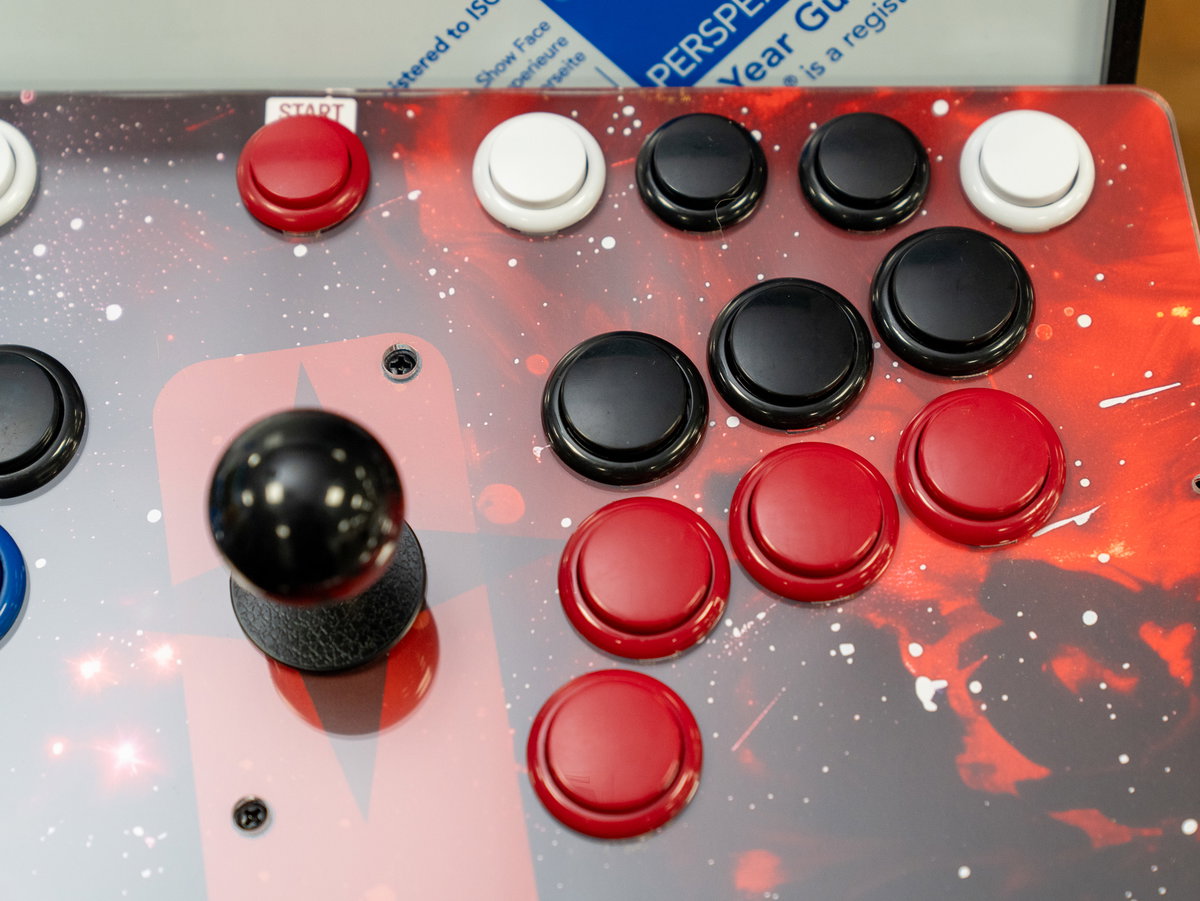
Here's a diagram of the button layout we're using. It has the A, B, X and Y buttons within easy reach, but also maps the L and R 1-3 buttons so you can play both retro and newer games. We're going to be using the button next to 'Start' as our hotkey button and the button on the side of the cabinet for '2P Start', but you could wire up these buttons the other way round if you prefer.
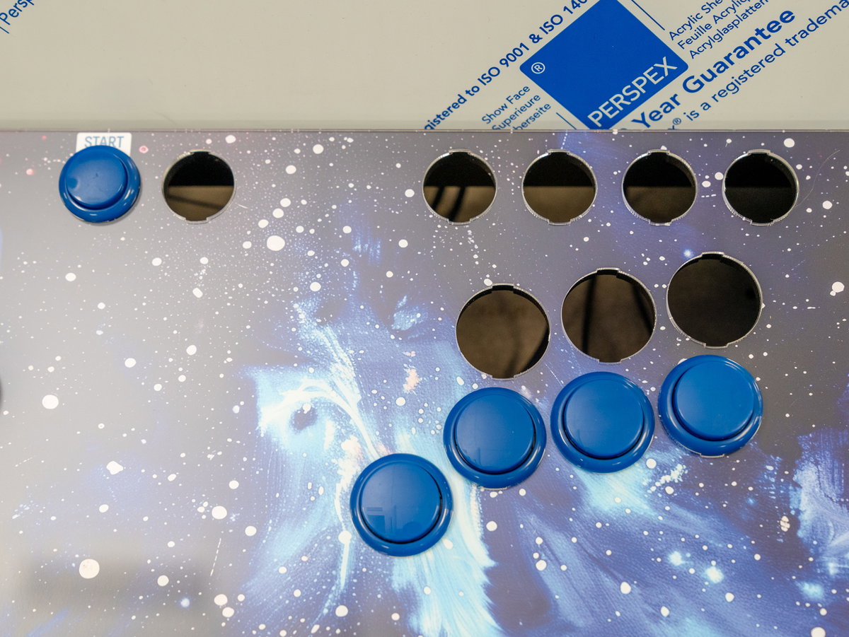
First we're adding the Start, A, B, X and Y buttons - poke the buttons (and the wires) through the holes in the console:
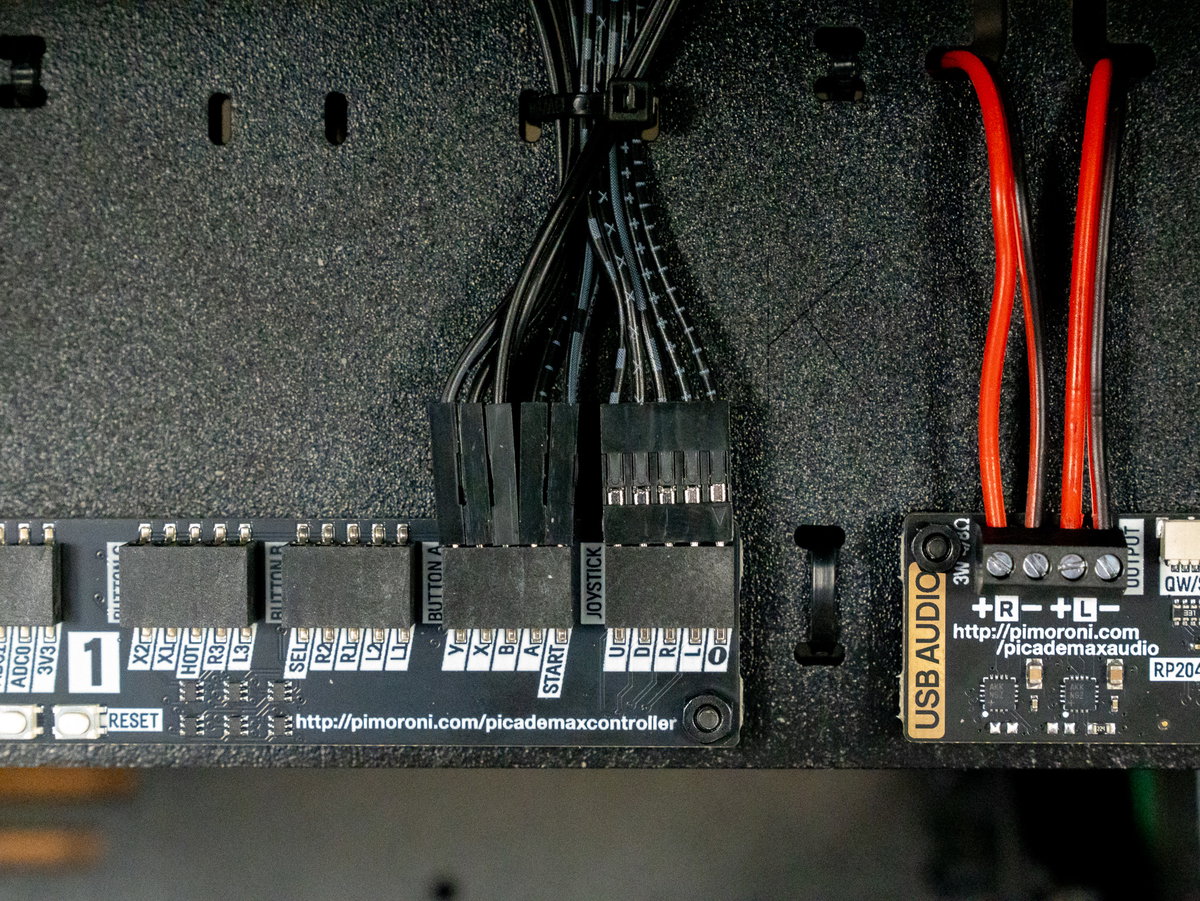
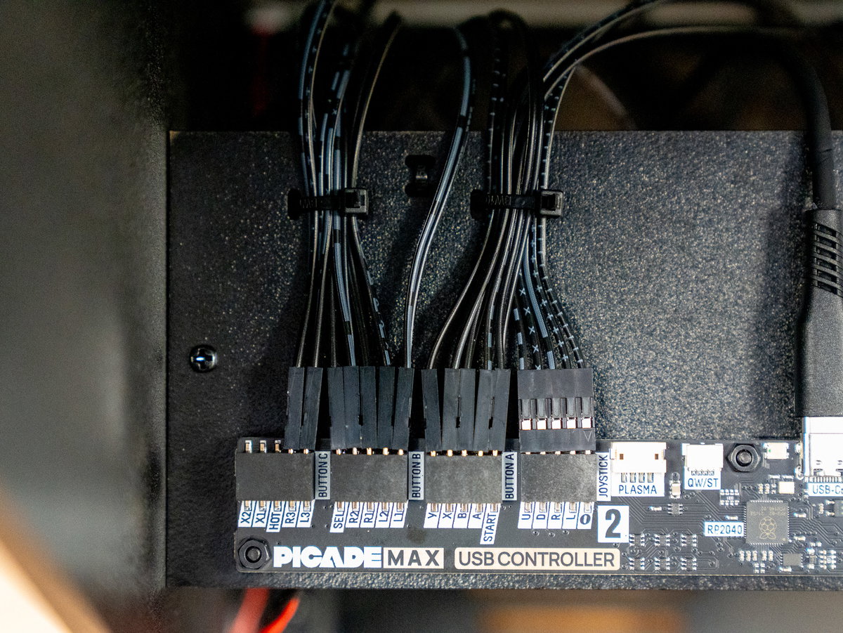
Thread the wires over the top of panel K and plug them into the appropriate connectors on the USB Controller board. We used cable ties as we went along to secure the cables to panel K in groups of 10.
Next we added the Hotkey, Select, and L and R buttons:
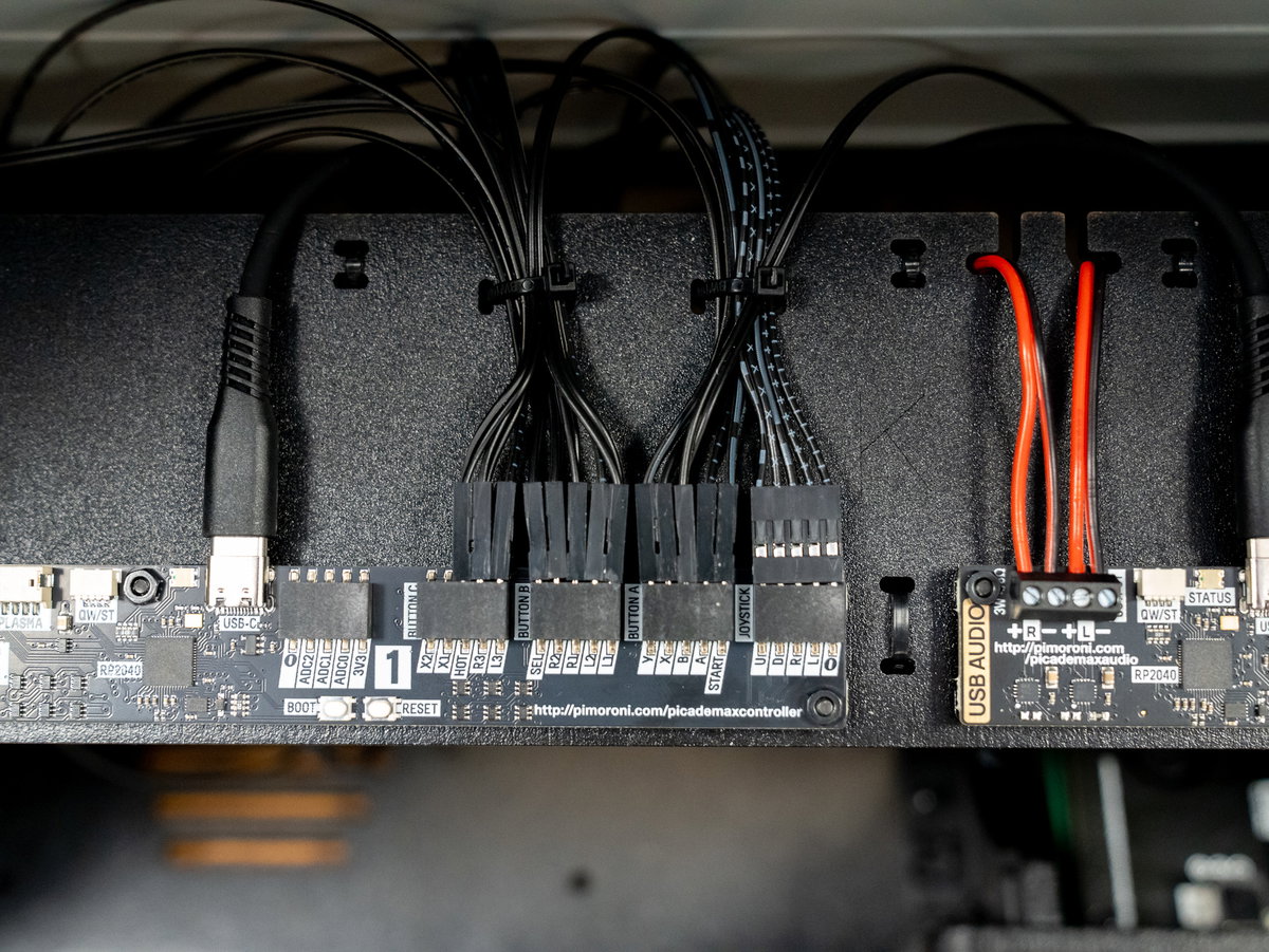
Next we'll wire up the side cabinet button.
Thread the wires and the button through the hole in panel D, from the outside.
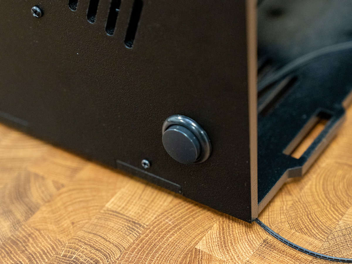
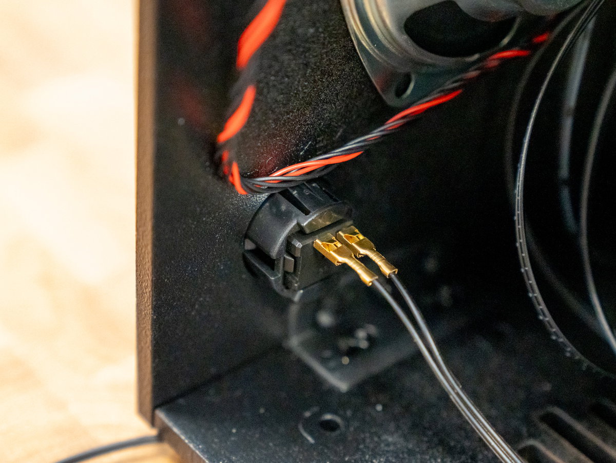
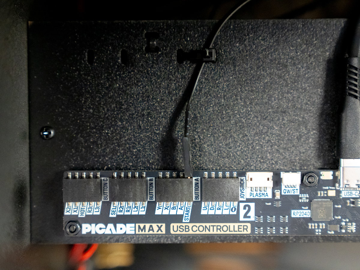
Then plug the DuPont pins on the other end of the wire into the 2 player START terminal on the Picade Max USB Controller board.
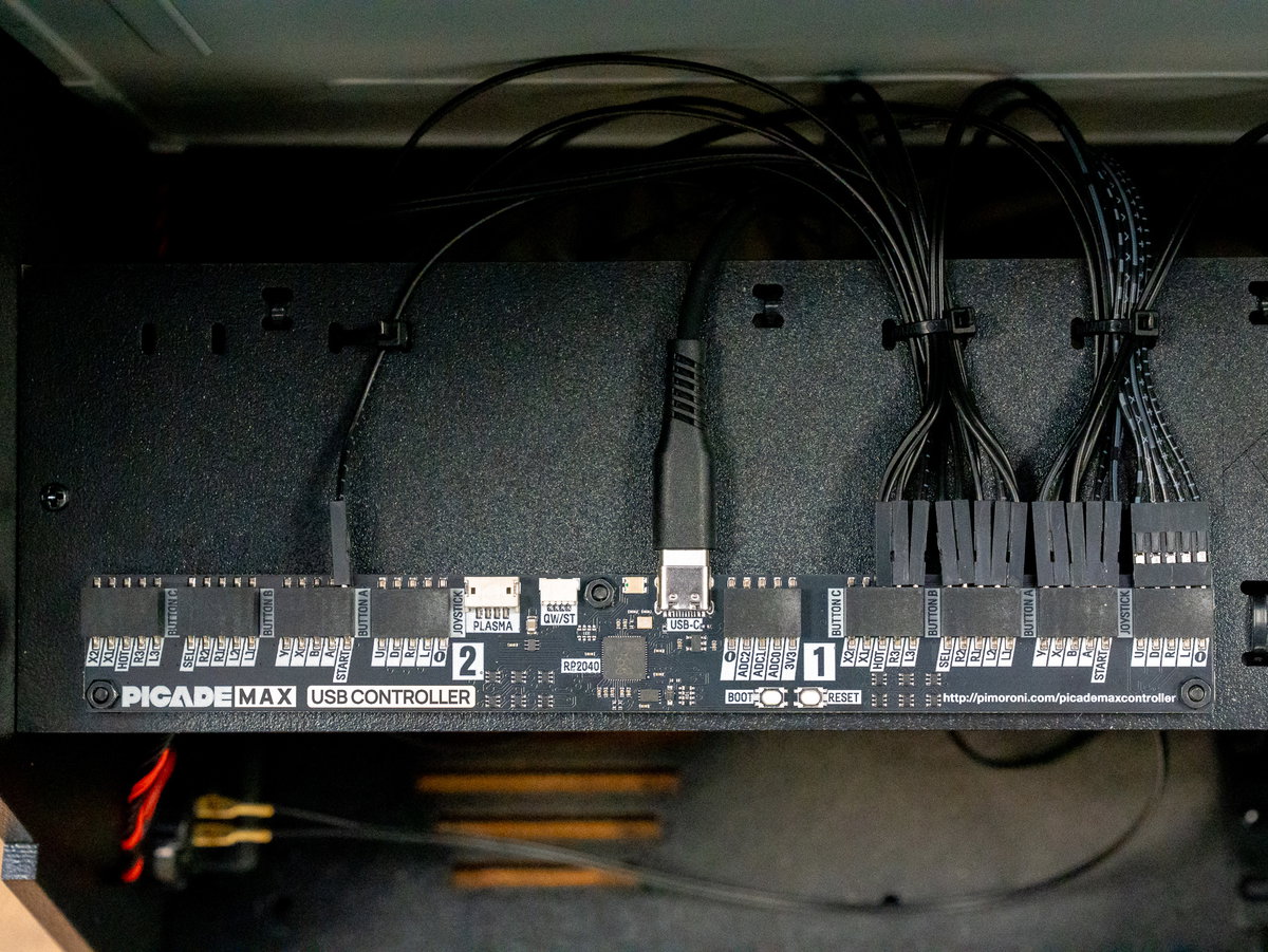
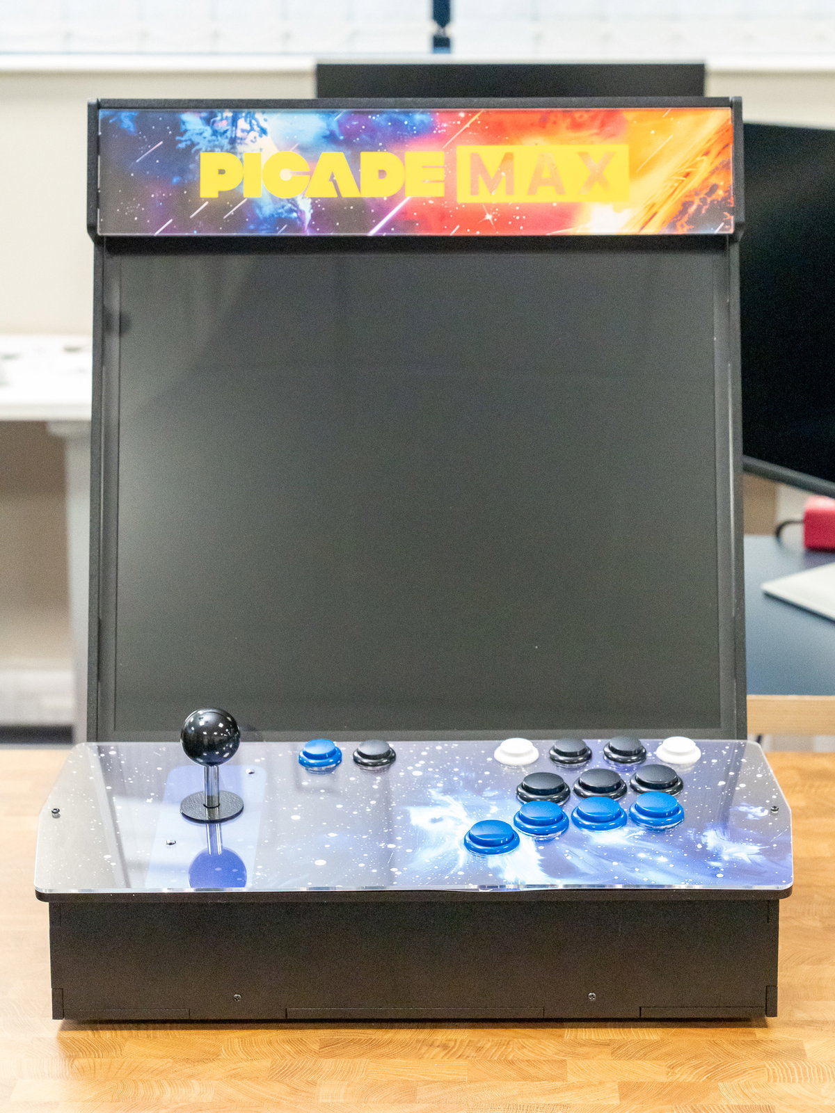
Here's what it looks like with all the buttons plugged in, and with everything tidied up with cable ties.

Console assembly (2 player)
Fitting the joysticks (2 player)
For this part you'll need:
- Wooden panel L (two player)
- 2x joysticks
- 2x 5 pin joystick cables from the wiring loom
- 4x M4 12mm screws
- 4x M4 nuts
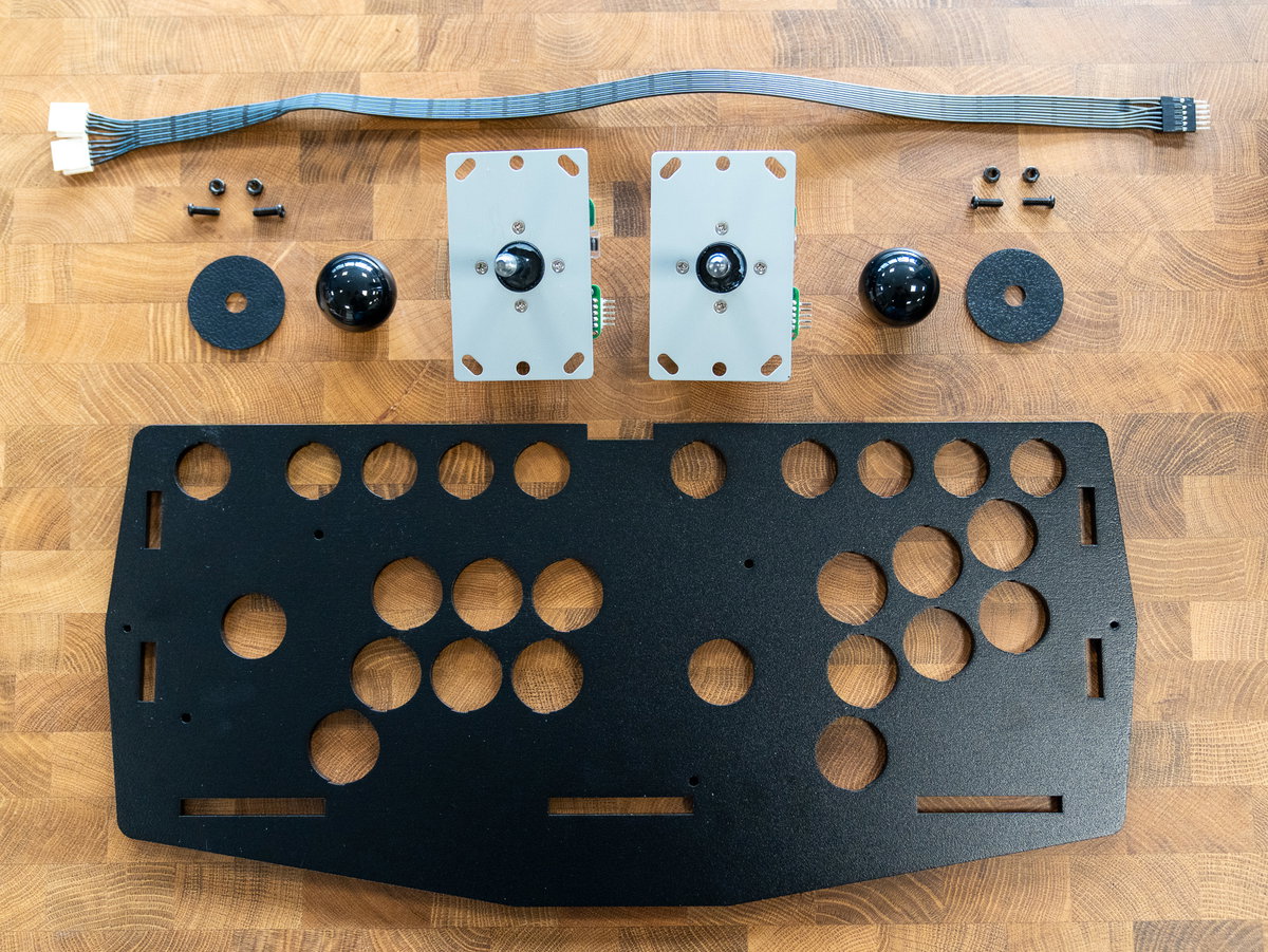
You'll also need the 2 player acrylic console panel and artwork:
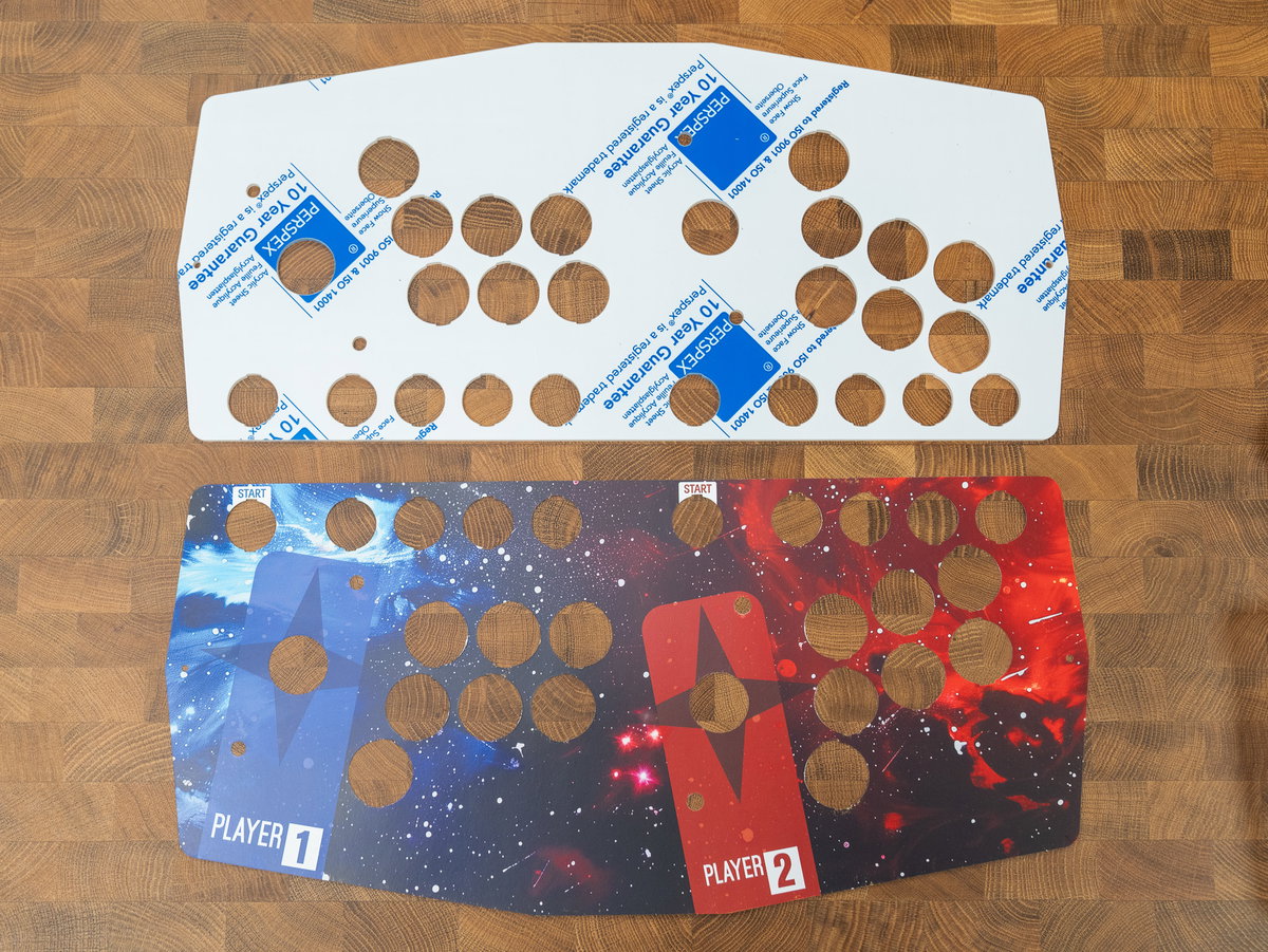
Flip over the wooden panel so that the label side is facing you. There are some markings to show you where to position the joysticks. If you're looking at the panel with the letter L the correct way up, the 5 pin connectors should be pointing out of the left hand side of the joysticks.
Use the M4 screws and nuts to secure the joysticks to the panel. Note that we're only using two of the four mounting holes for each joystick.
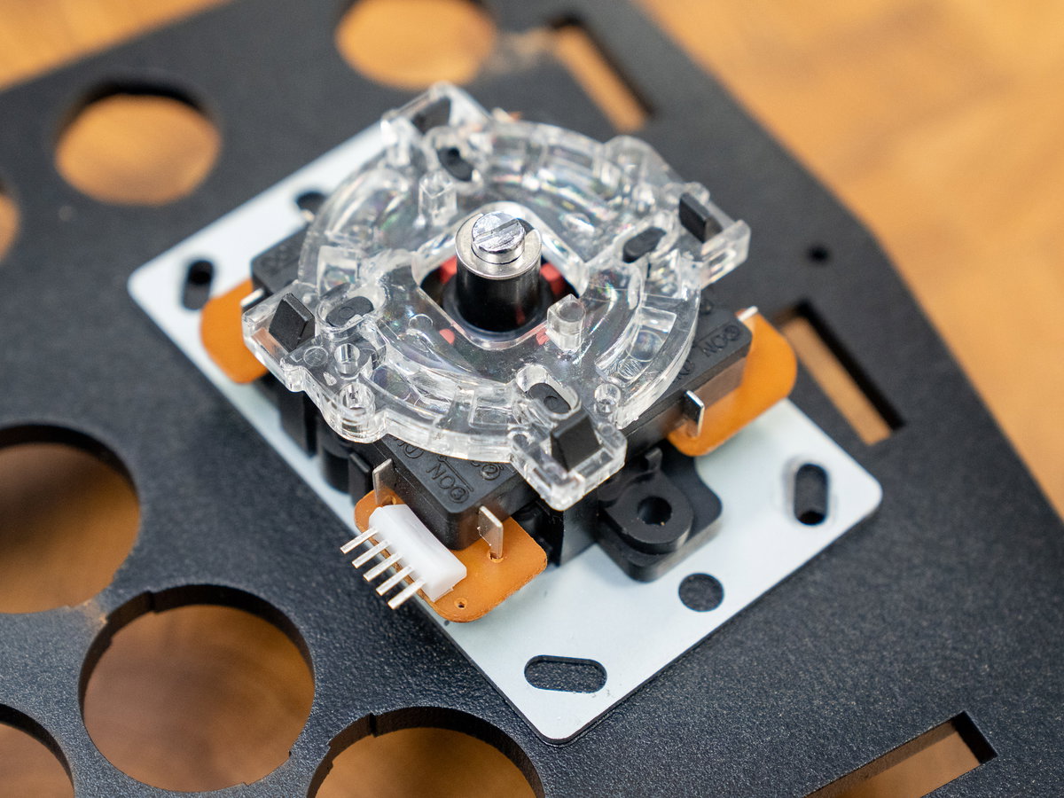
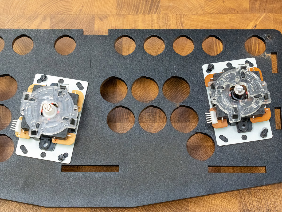
Split the joystick cable into two separate cables.
Use the chunky beige connectors to attach the cables to both joysticks.
The 5 pin connectors on the joysticks are made of quite soft metal and can sometimes get a little squashed during transit. You might need to bend the pins slightly to straighten them out if you're having trouble plugging in the connectors.
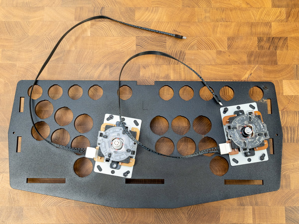
Position the console panel in front of the cabinet and poke the joystick cables into the cabinet from the front.
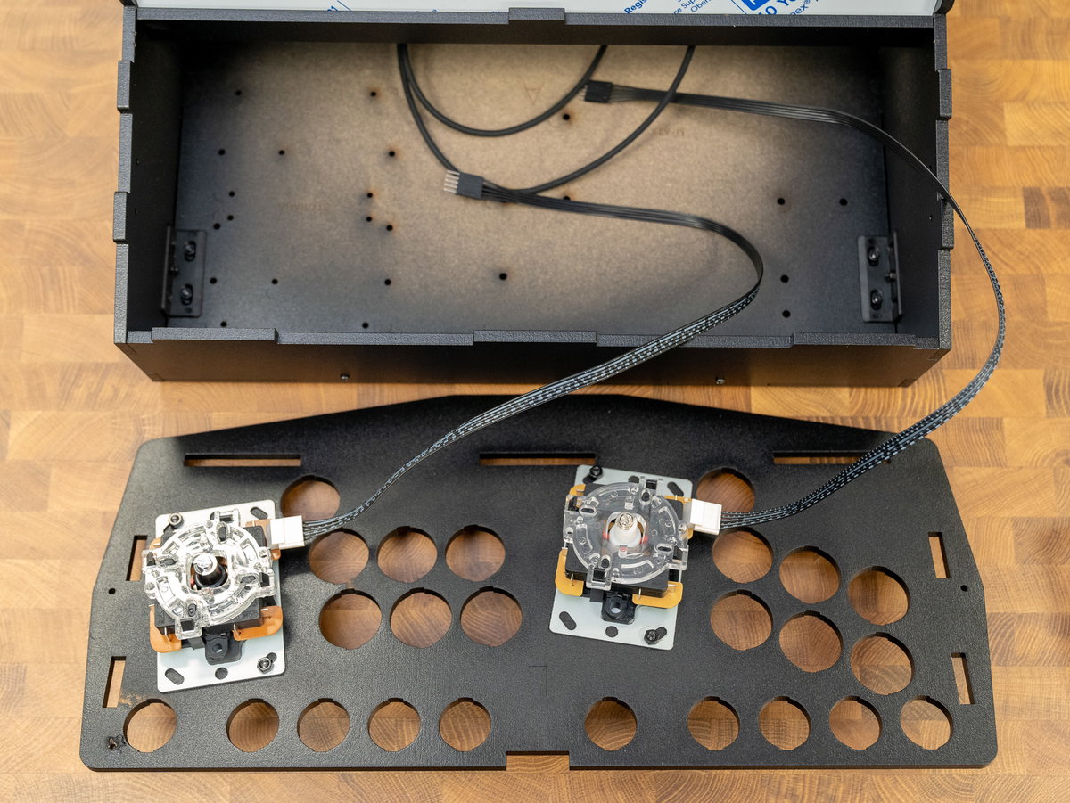
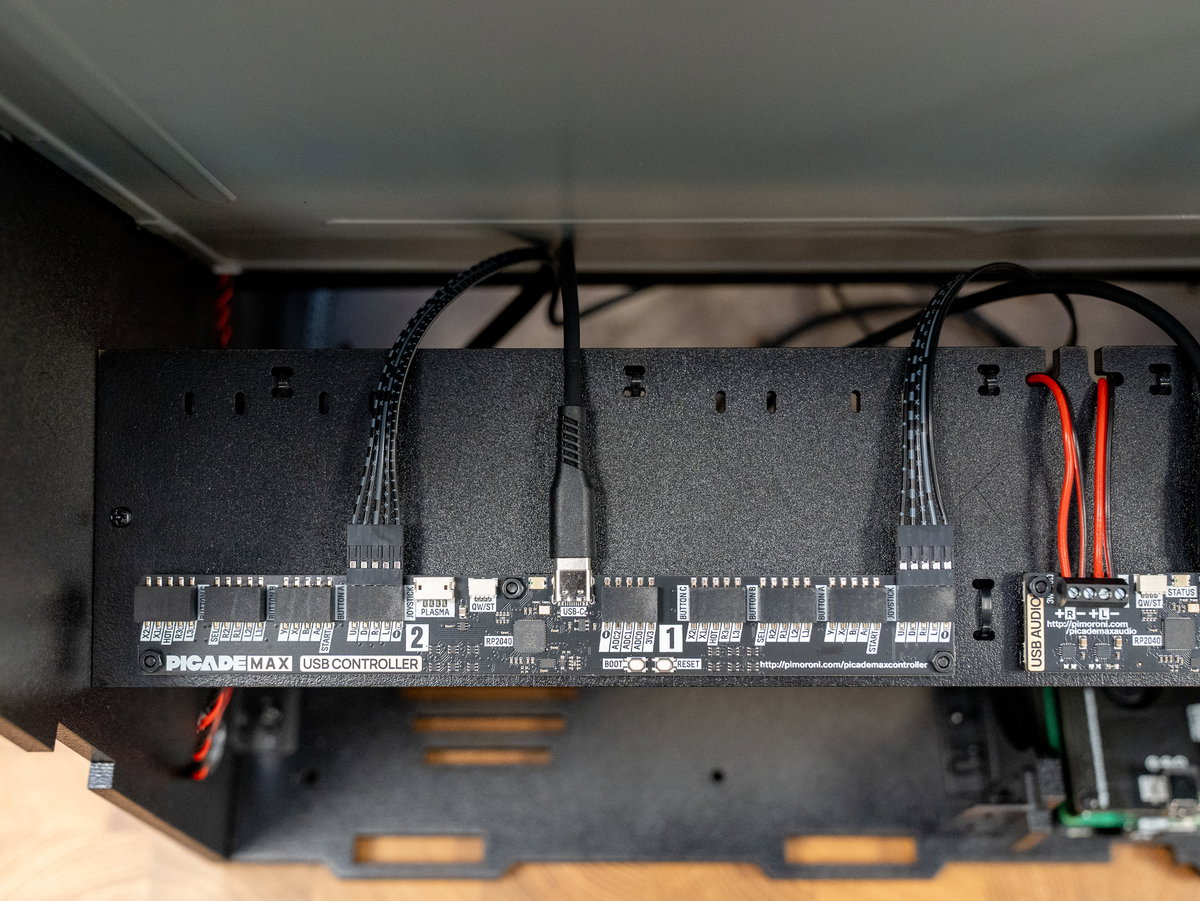
Feed the joystick cables up over the top of panel K and plug them into the connectors on top of the Picade Max USB Controller board. The connectors on the joystick cable have a little moulded arrow to show you where the ground wire is - match this up to the - marking on the board. You can also check that the printed grey markings on the joystick cables are facing towards you.
(If you find that only the 'up' direction is working on your joystick, you've probably got the connector orientation wrong - try unplugging the connector at the Picade Max USB Controller end, flipping it 180° and plugging it in again).
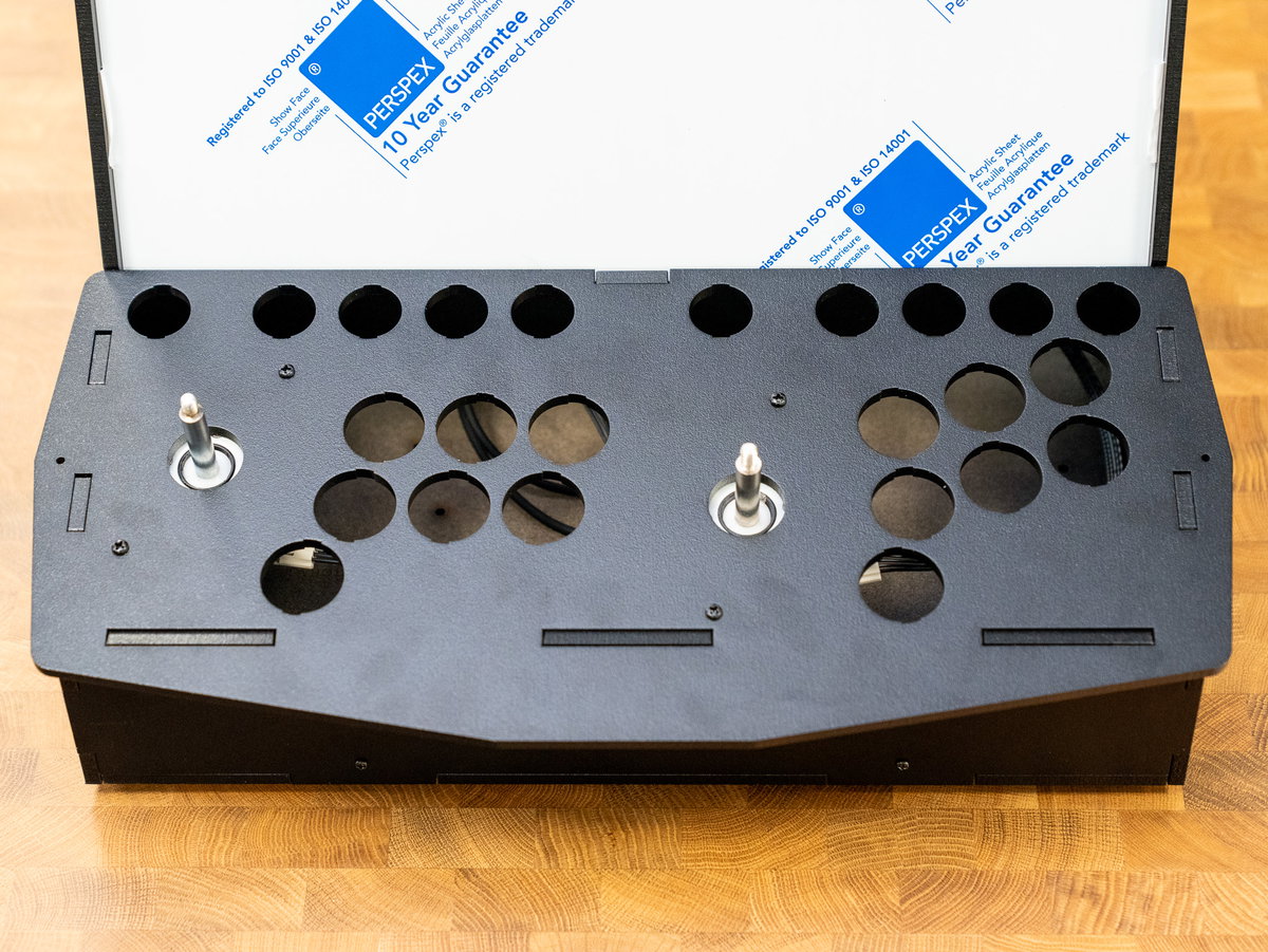
Now that the joysticks are attached, flip the console assembly over and place it in its final position on the front of the Picade. We're not fastening it down yet though, you might find it useful to be able to flip it upside down whilst wiring up the buttons.
Next, place your cardboard console artwork on top of the console assembly, art side up and with the holes matching up.
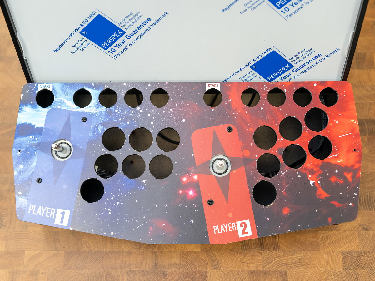
Take your acrylic panel and identify the underside (the underside of the two player one looks like this):
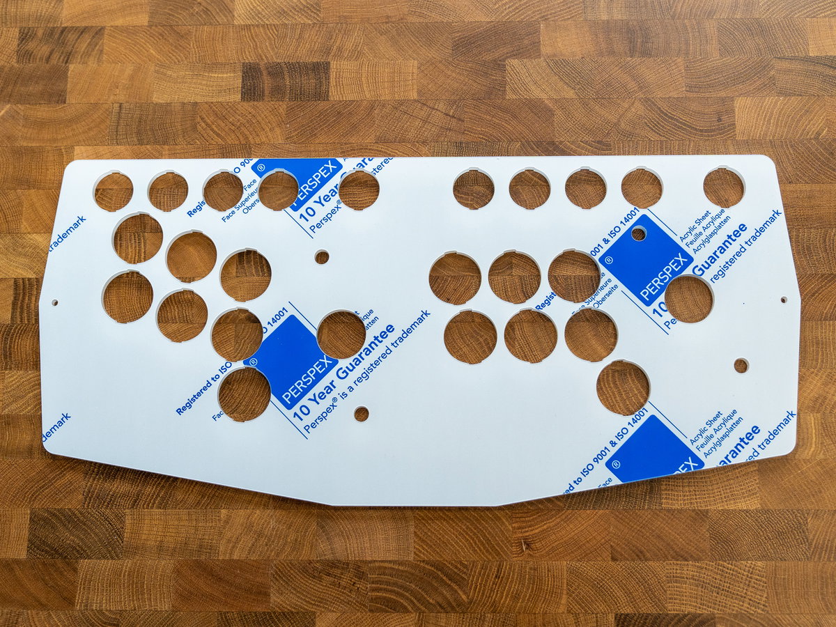
Remove the protective coating from the underside of the acrylic.
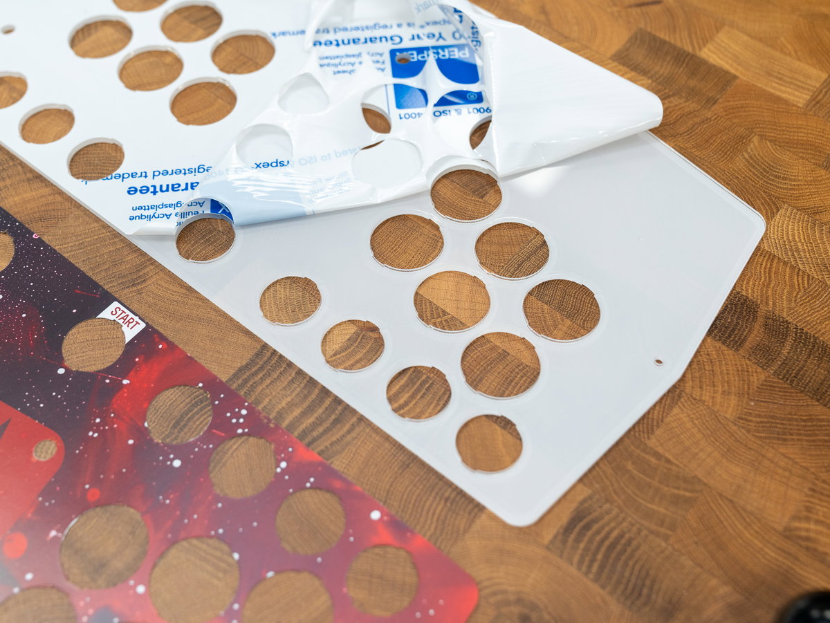
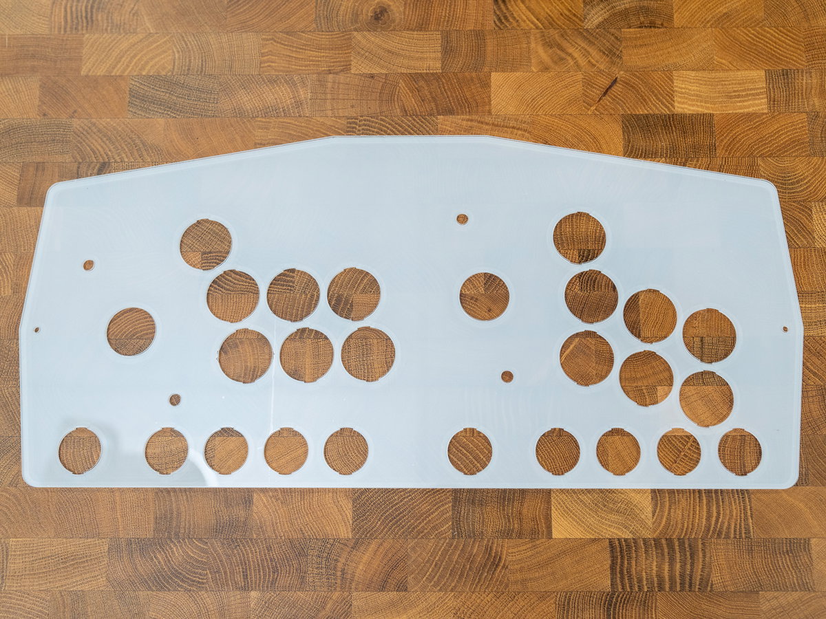
Then flip the acrylic piece over and place it on top of the console assembly, so that the freshly peeled side is touching the art.
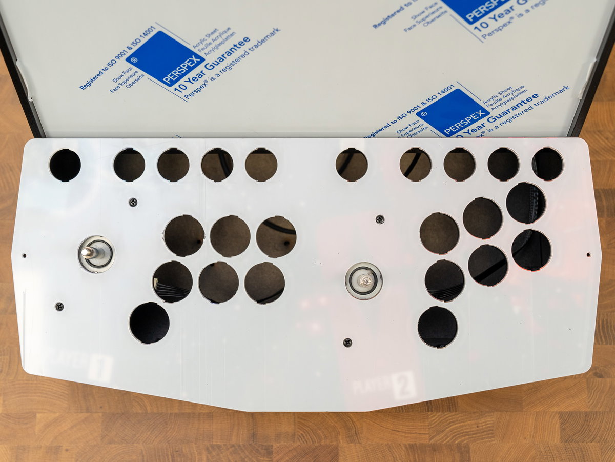
It's easiest to remove the protective layer from the top side of the acrylic now, though it is possible to leave it on until later if you want to. If you leave it until after you've fitted the buttons, you'll probably need to remove it in pieces.
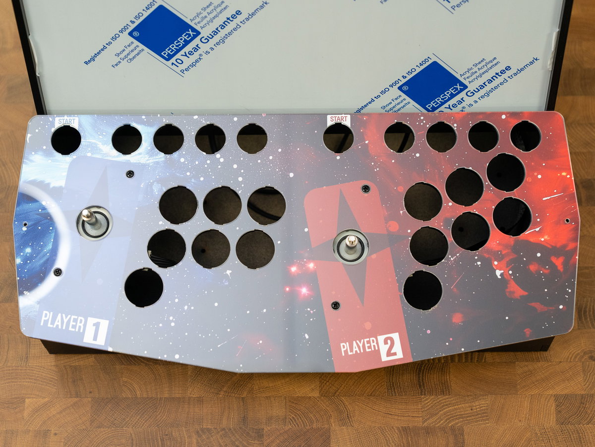
Add the collars and screw on the joystick balls.
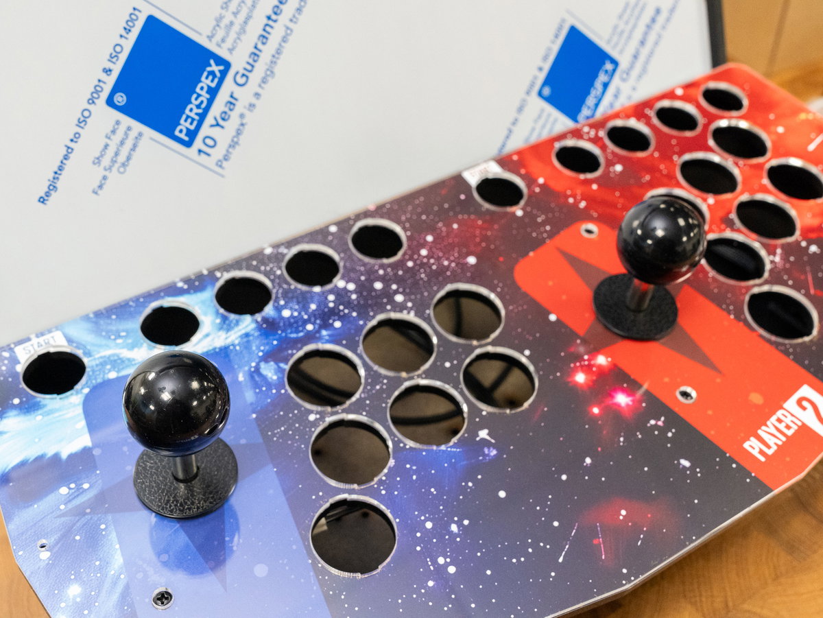
Fitting the buttons (2 player)
For this section you'll need:
- The 24 and 30mm arcade buttons
- The DuPont pin to spade connectors cables (from the wiring loom)
For the 2 player layout, we're using:
- 6x 30mm black button
- 4x 30mm blue button
- 4x 30mm red button
- 4x 24mm black button
- 1x 24mm blue button
- 1x 24mm red button
- 4x 24mm white button
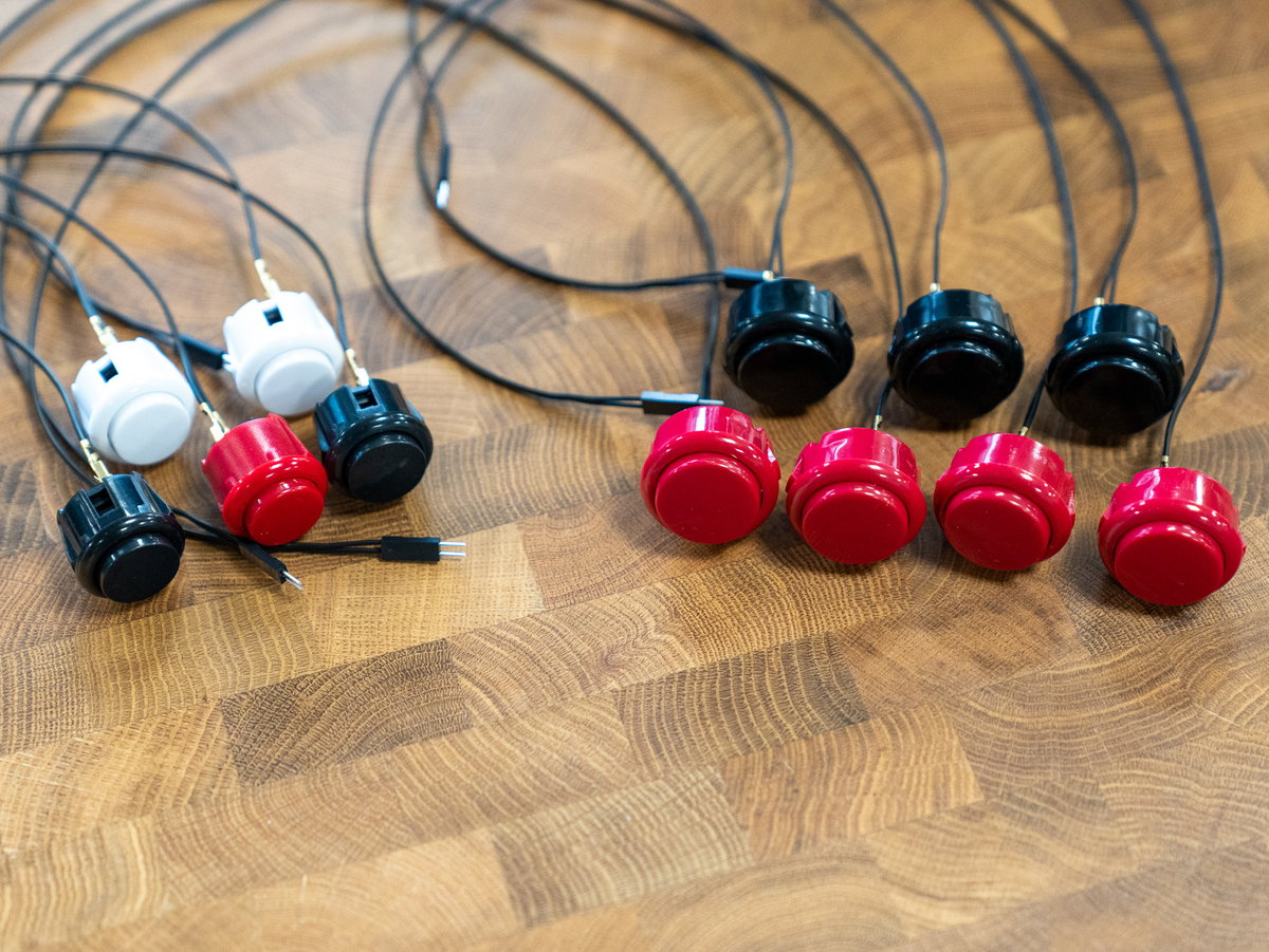
- 24x DuPont pin to spade connectors cables (from the wiring loom)
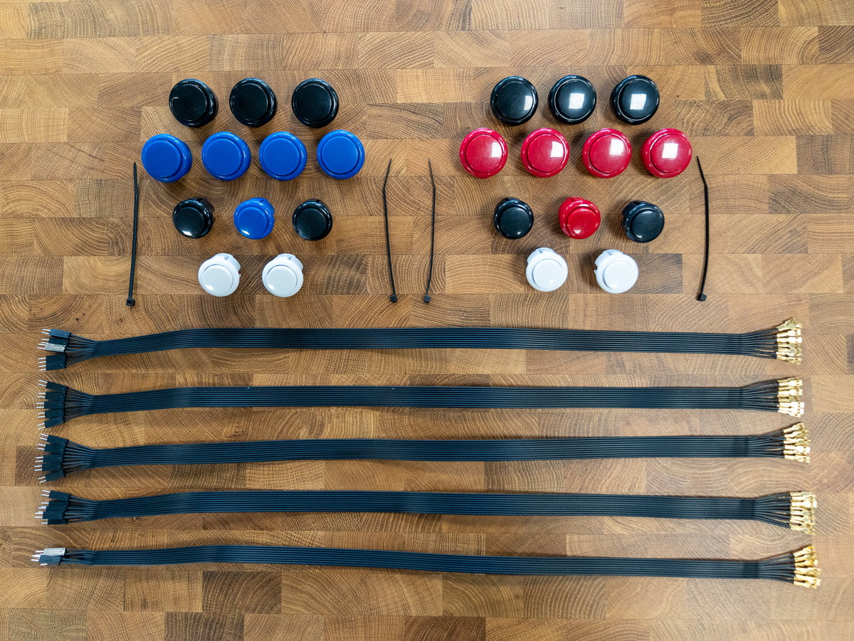
Separate the cables from the wiring loom into pairs of wires - each pair should have two DuPont pin connectors on one end and two spade connectors on the other. Push the spade connectors onto the terminals on each button.
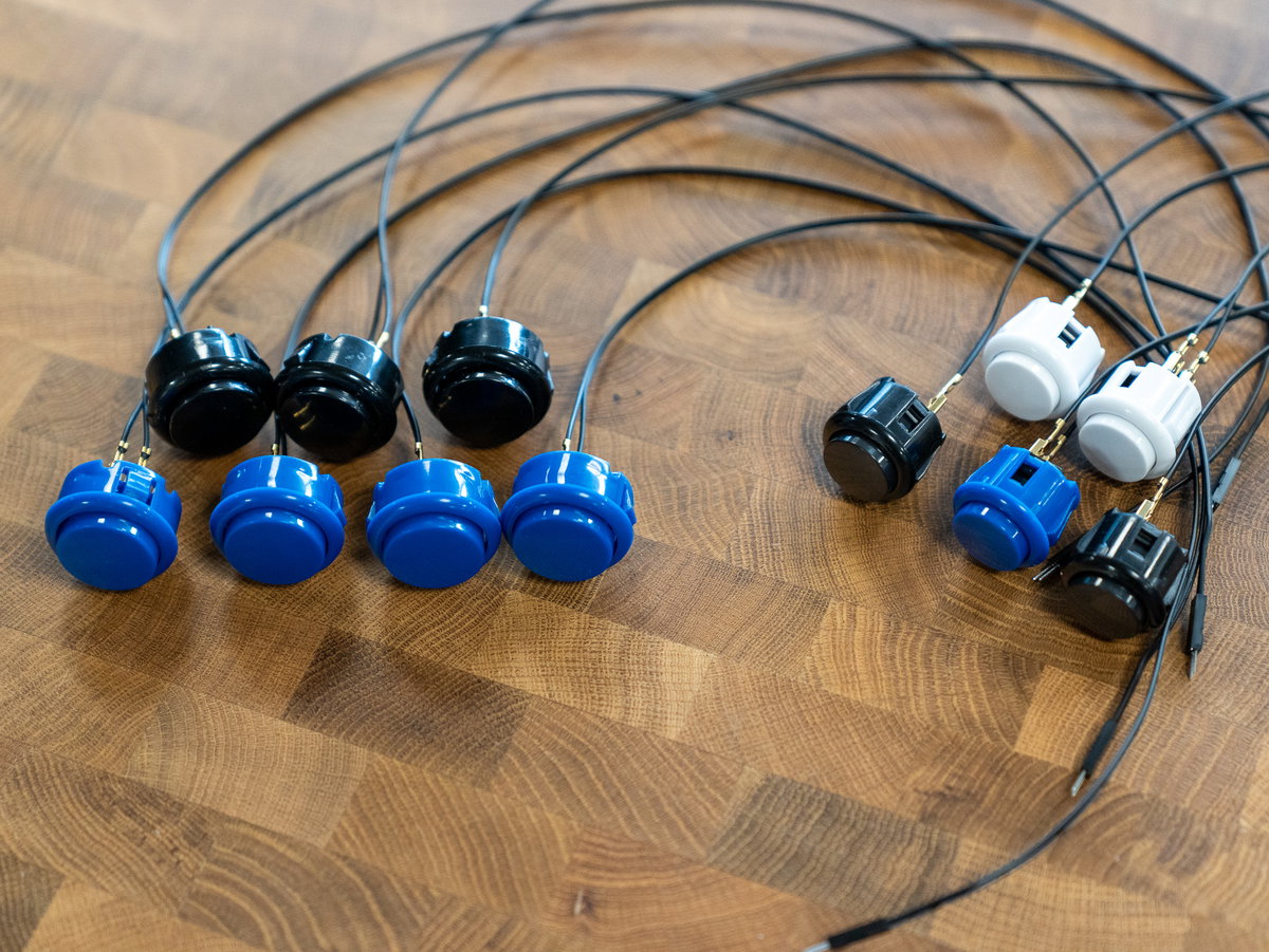
Here's a diagram of the button layout we're using. It has the A, B, X and Y buttons within easy reach, but also maps the L and R 1-3 buttons so you can play both retro and newer games. With the two player layout, we're using the button on the side of the cabinet as the hotkey button.
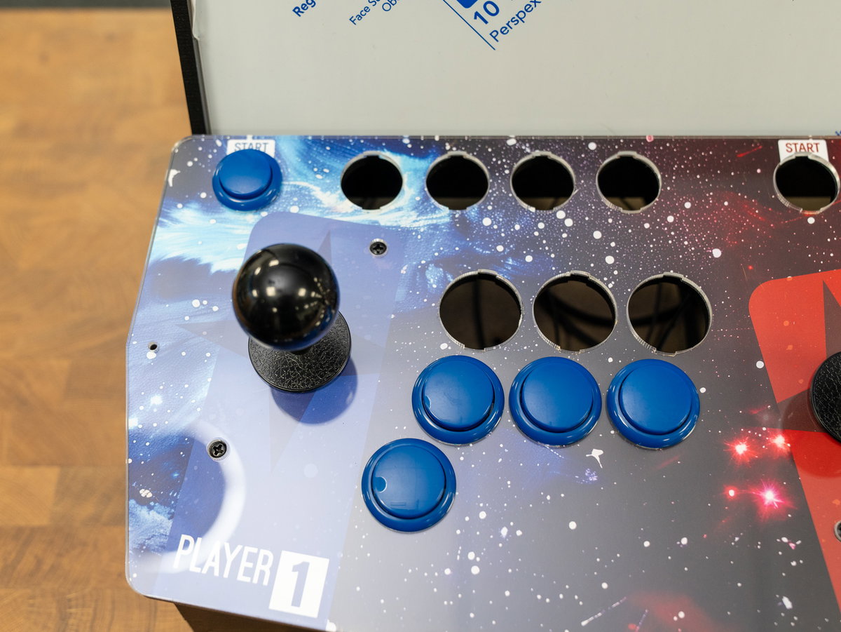
First we're adding player one's Start, A, B, X and Y buttons - poke the buttons (and the wires) through the holes in the console:
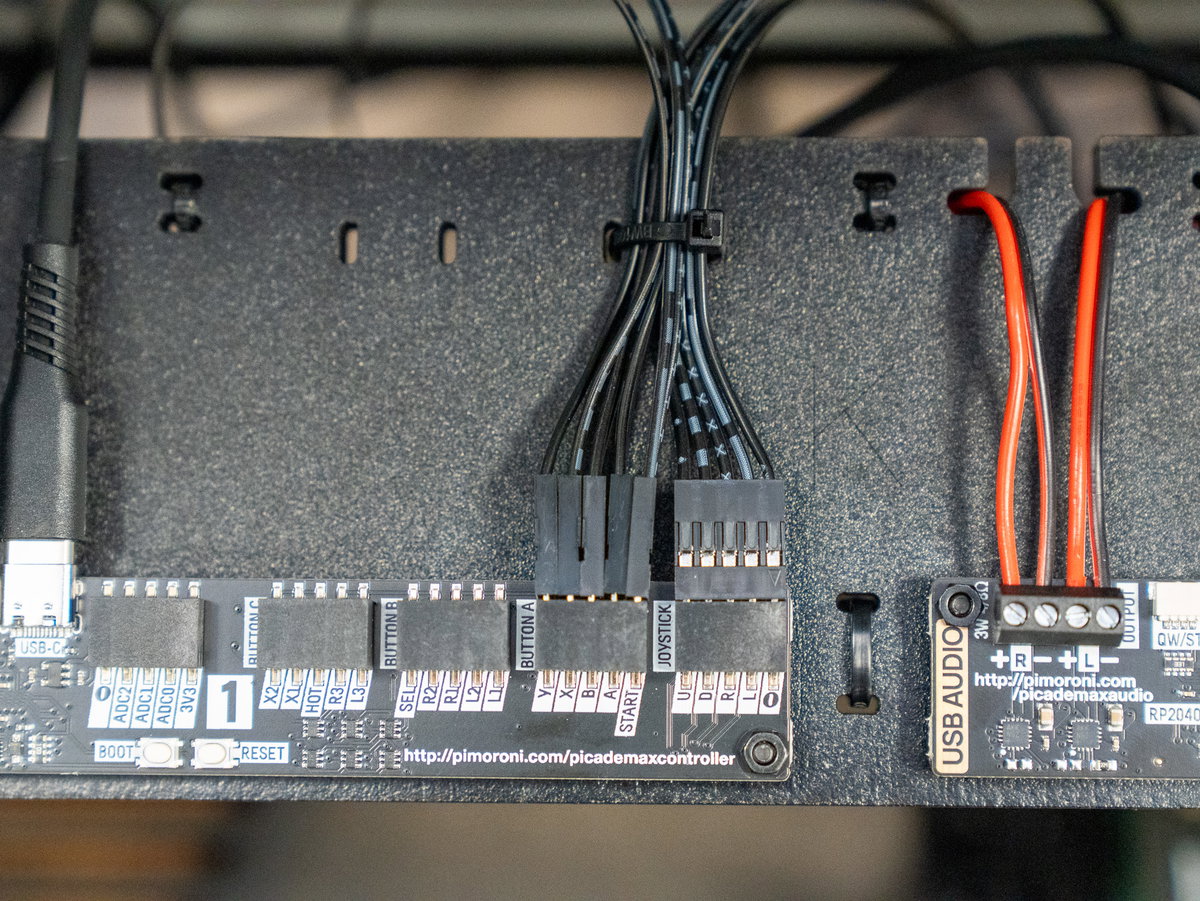
Thread the wires over the top of panel K and plug them into the appropriate connectors on the USB Controller board. We used cable ties as we went along to secure the cables to panel K in groups of 10.
Next we added the Select, and L and R buttons:
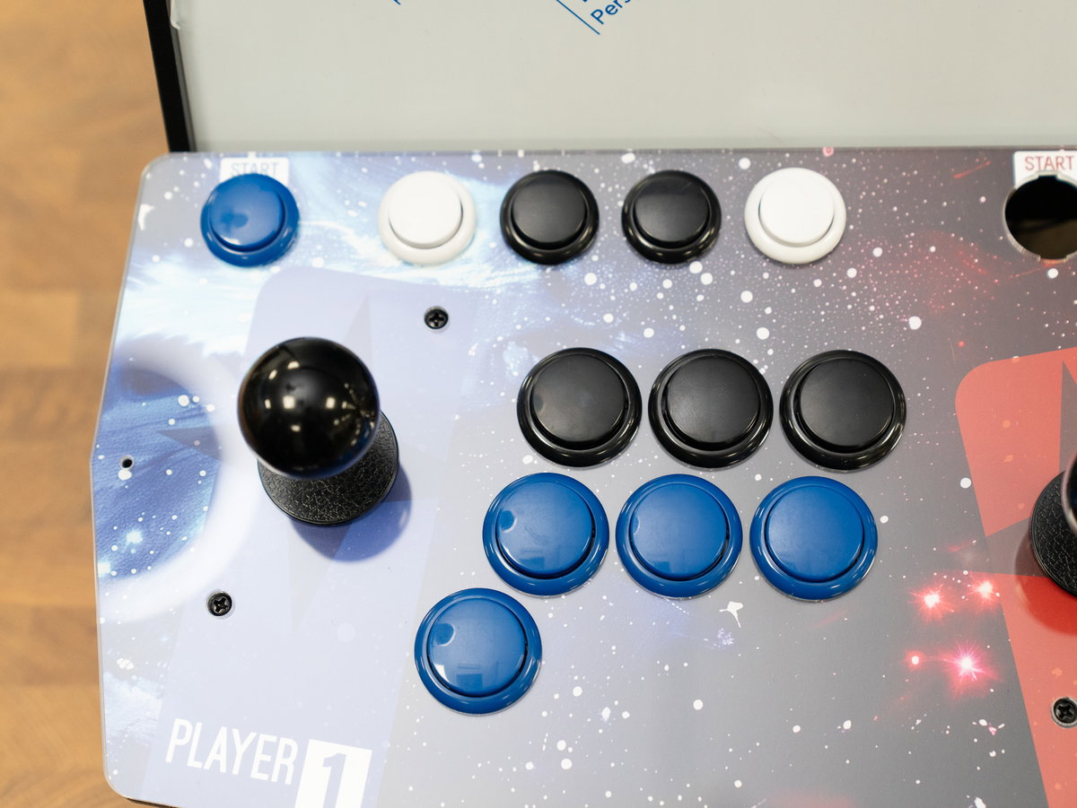
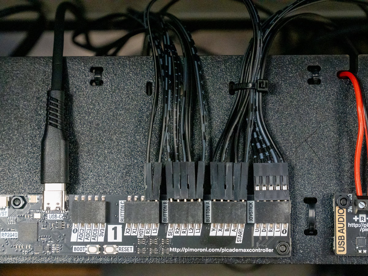
And player 2's buttons:
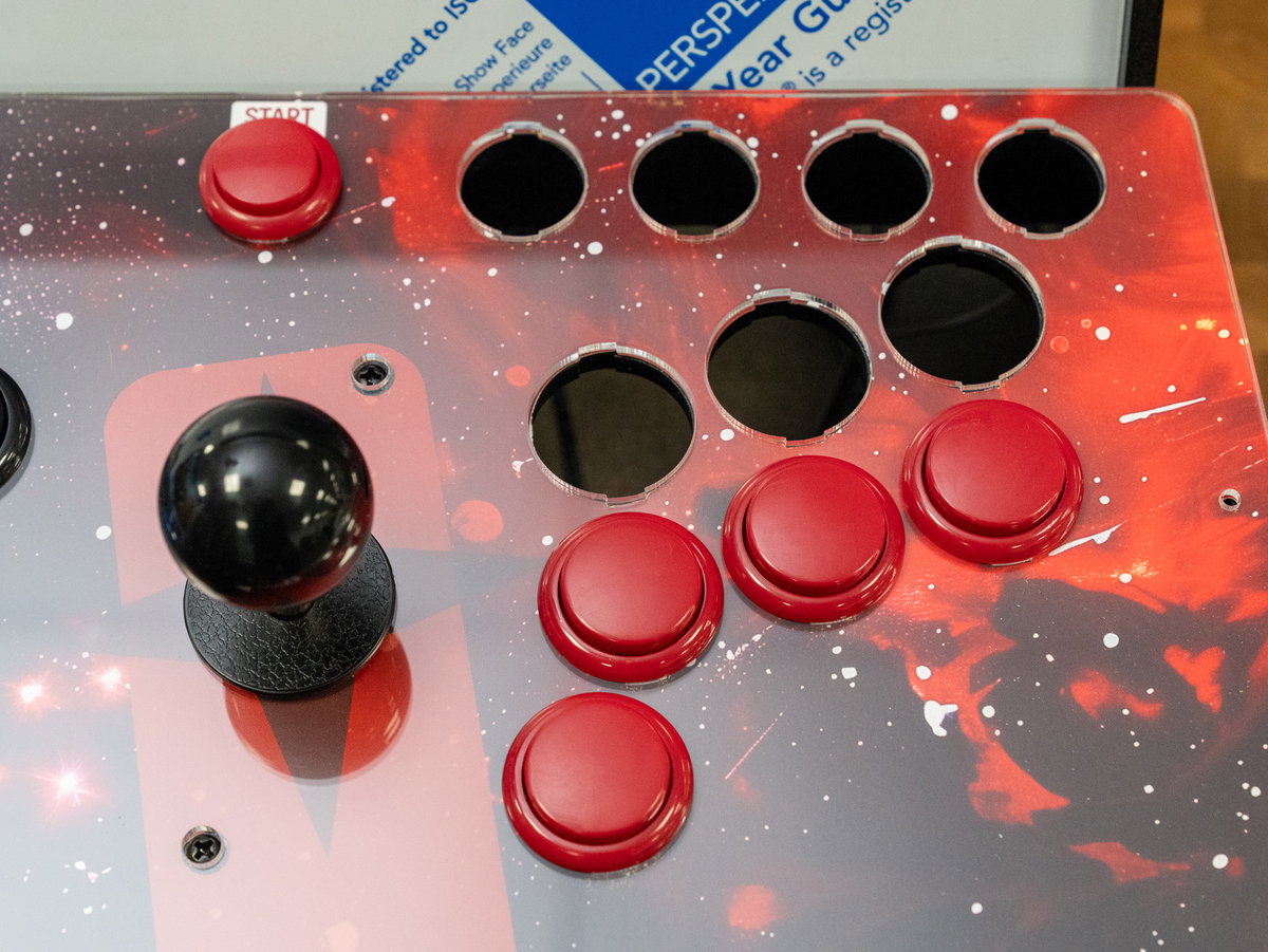
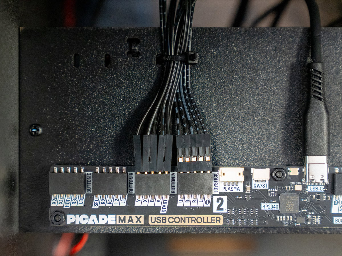
Next we'll add the side button to the cabinet. For this step you'll need:
- 1x 24mm arcade button (small)
- 1x DuPont pin to spade connectors cable (from the wiring loom)
We've included a couple of extra small buttons, so you can choose what colour you like for the side button.
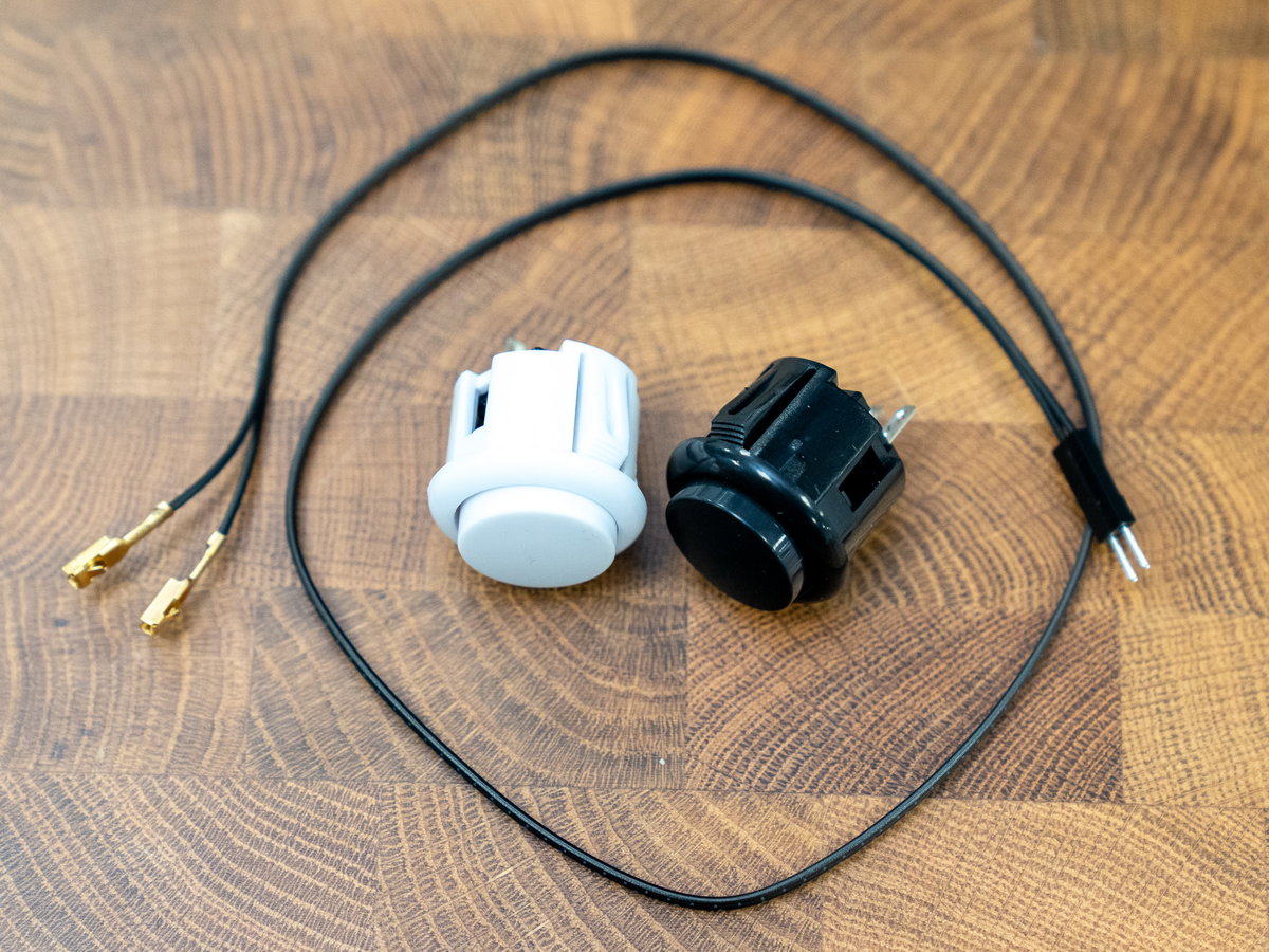
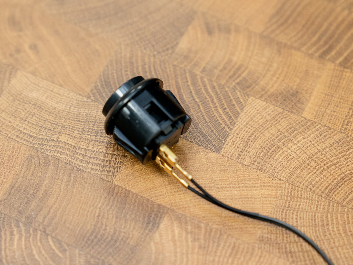
Attach the wires to the button as before.
Thread the wires and the button through the hole in panel D, from the outside.
Then plug the DuPont pins on the other end of the wire into the HOT terminal on the Picade Max USB Controller board.
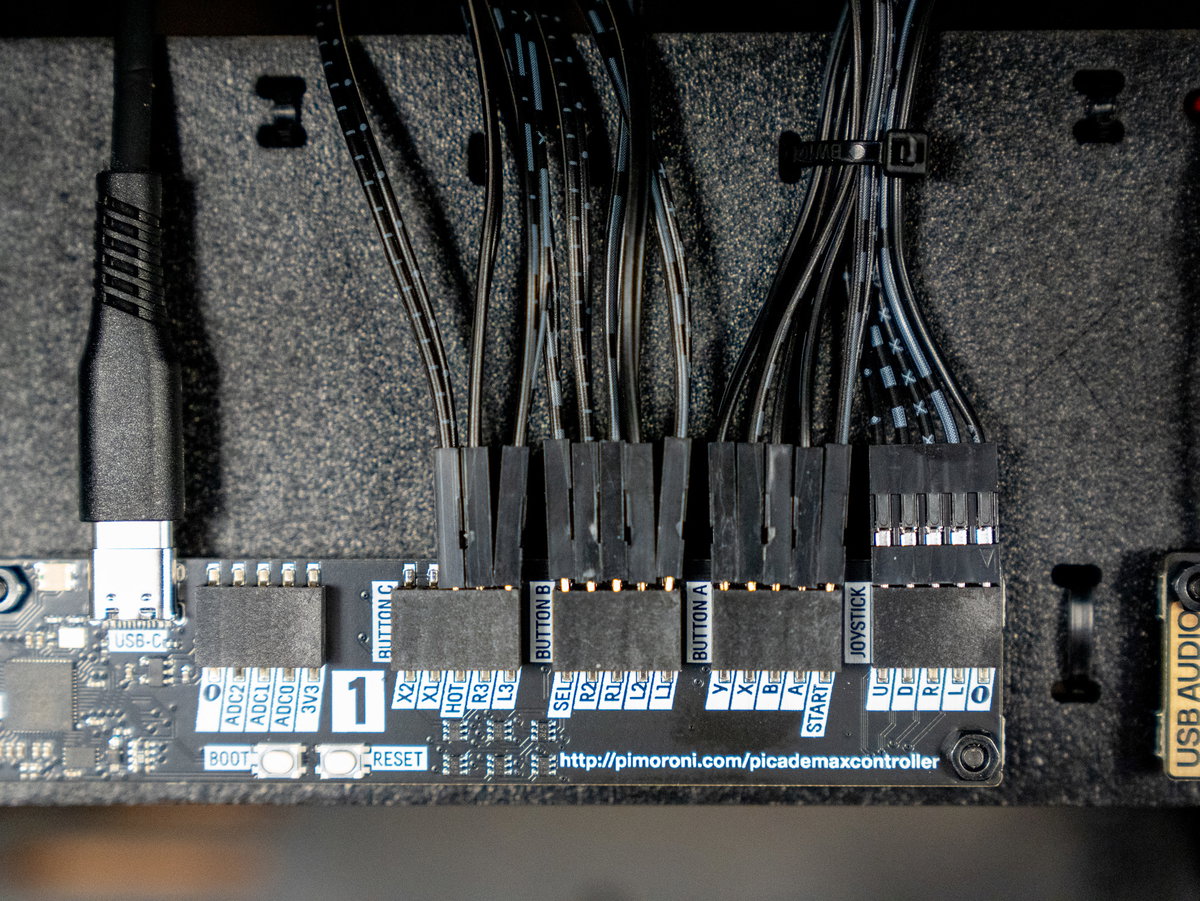
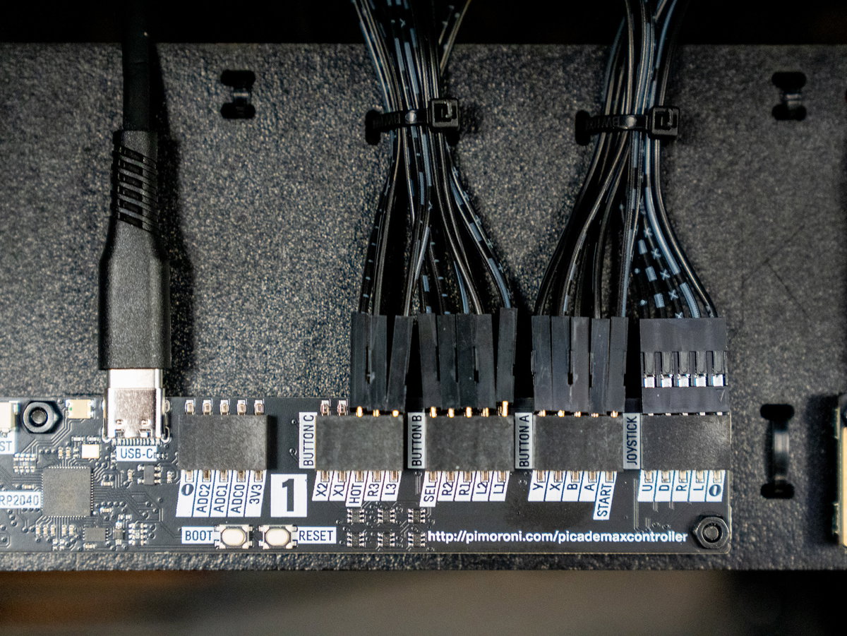
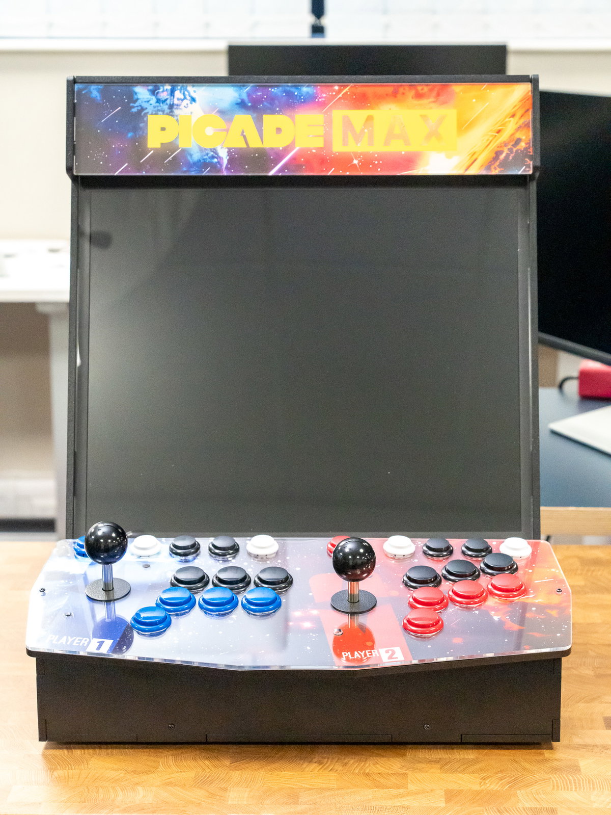
Here's what it looks like with all the buttons plugged in, and with everything tidied up with cable ties.
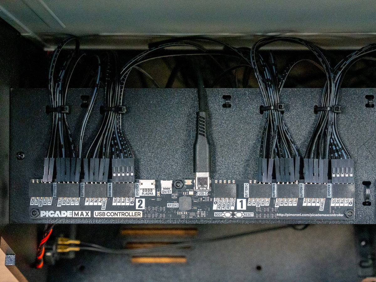
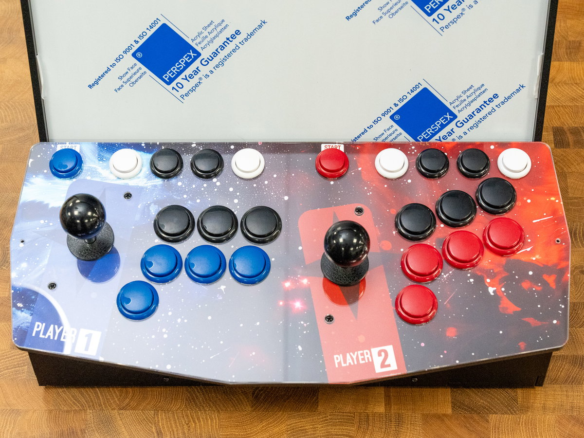
Adding the backplate
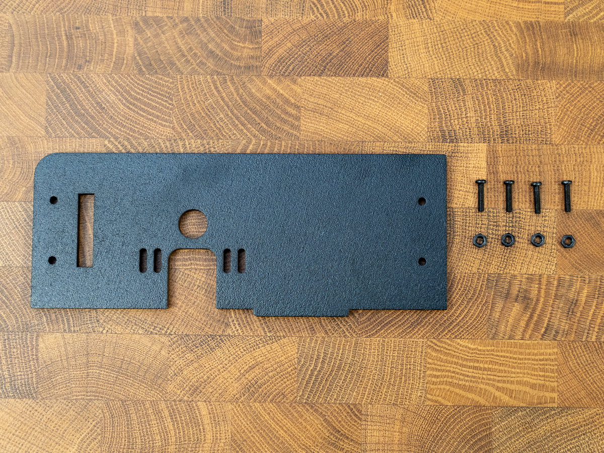
Next we'll be adding the backplate. There are two versions included (panels I and J) - as we're using a Raspberry Pi we'll be using panel J which has a round cutout for your Picade's power cable to pass through. It also has a cutout to make it possible to insert/remove the SD card.
Panel I is for if you are going down the mini PC route and want to install a big old PC power supply in the cabinet.
Assuming you're using a Raspberry Pi, you'll need:
- Wooden panel J
- 4x M3 12mm screws
- 4x M3 nuts
Insert the tab on panel B into the slot on panel J:
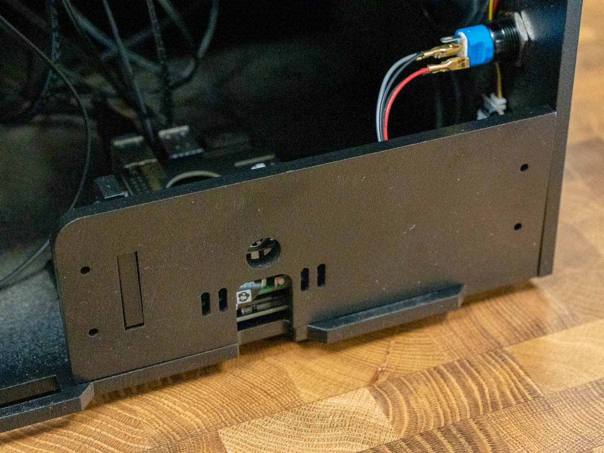
Then attach it in place through the brackets using the M3 12mm screws and nuts.
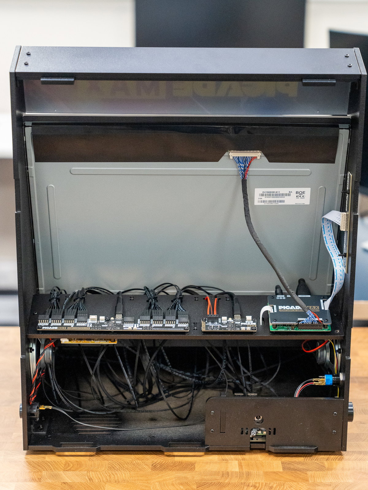
Final cabinet assembly
For this section you'll need:
- Wooden panel N (the big back piece)
- 2x black plastic brackets
- 2x long M3 18mm screws
- 4x short M3 12mm screws
- 6x M3 nuts
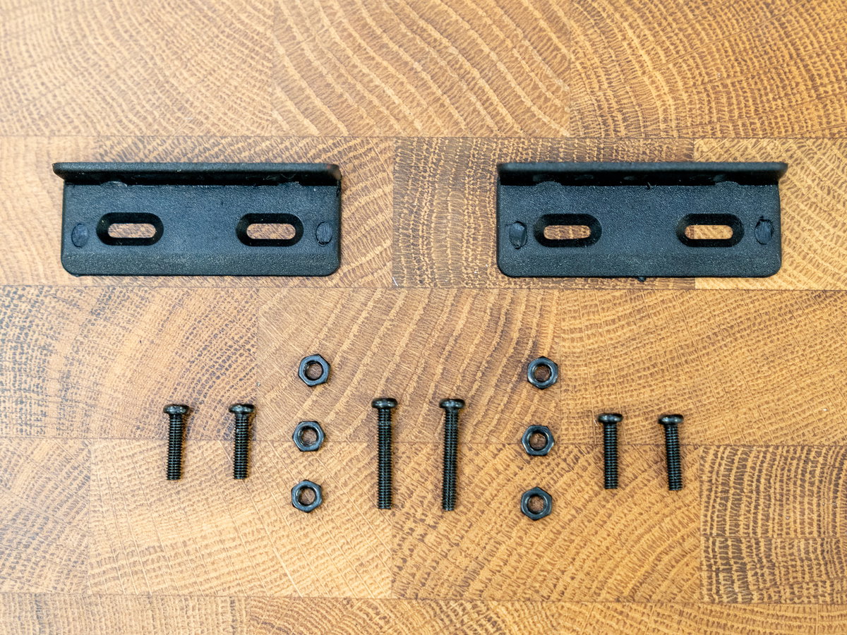
Remove the console from the cabinet temporarily.
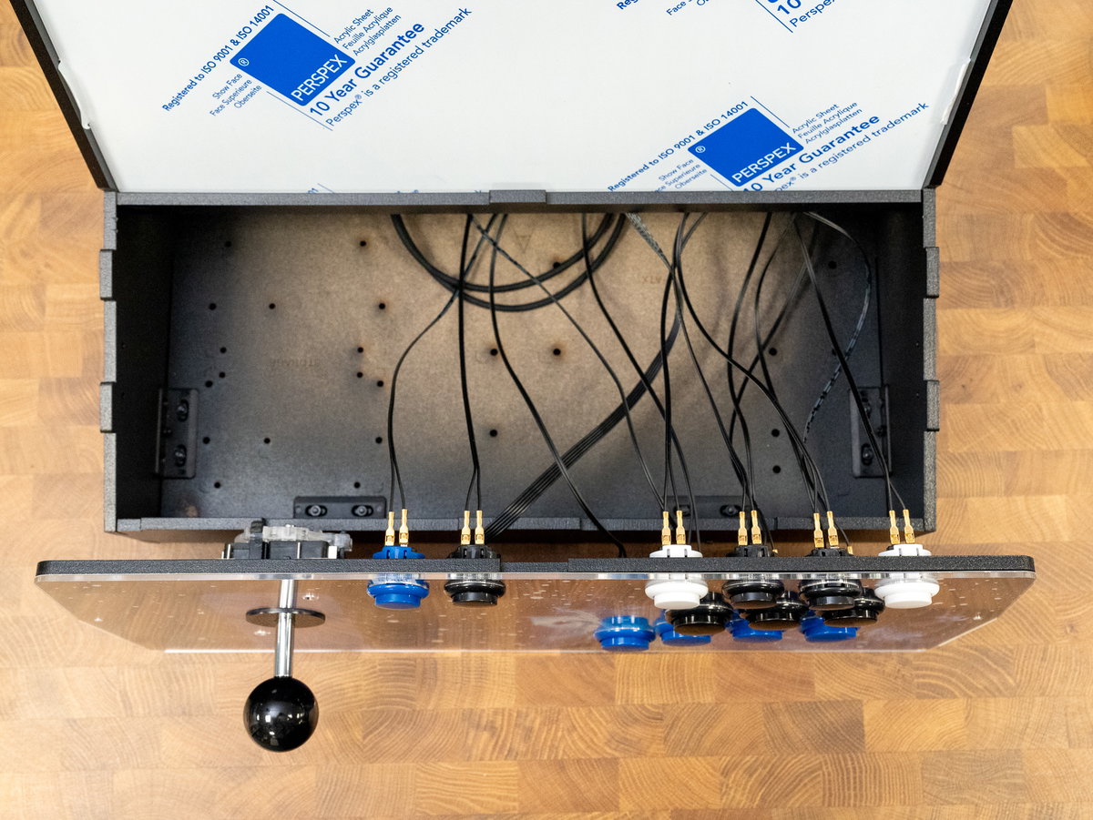
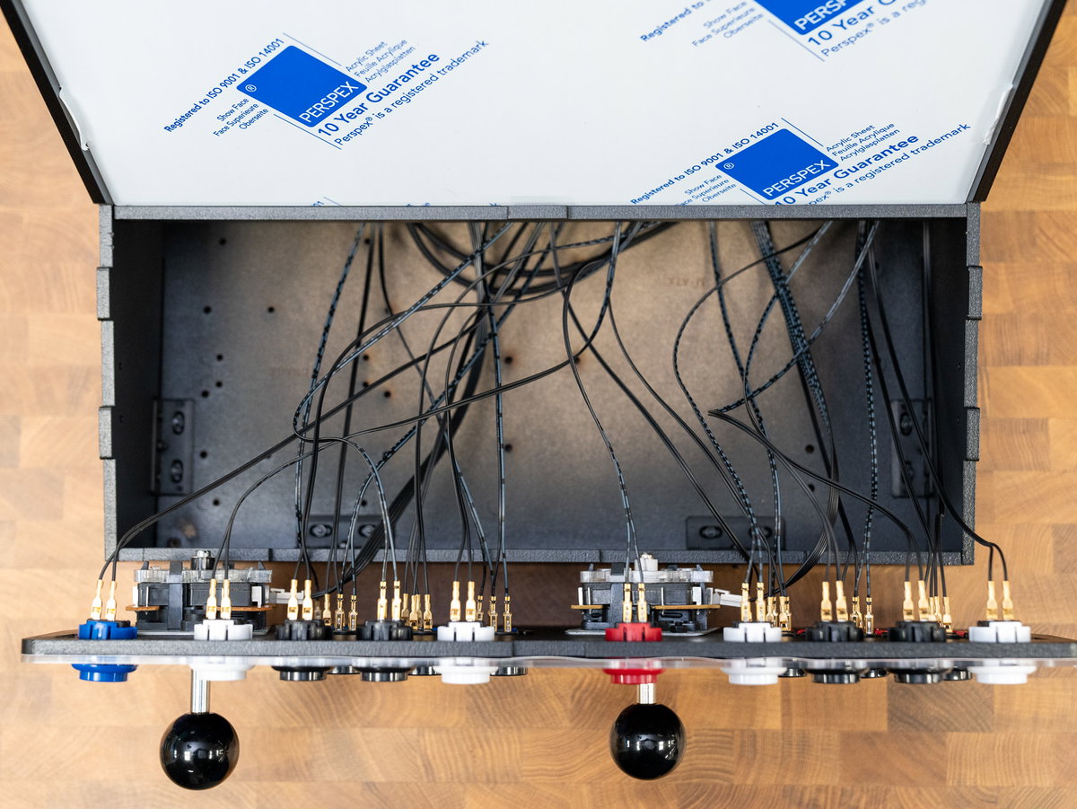
Attach the side brackets to the cabinet, using 12mm screws.
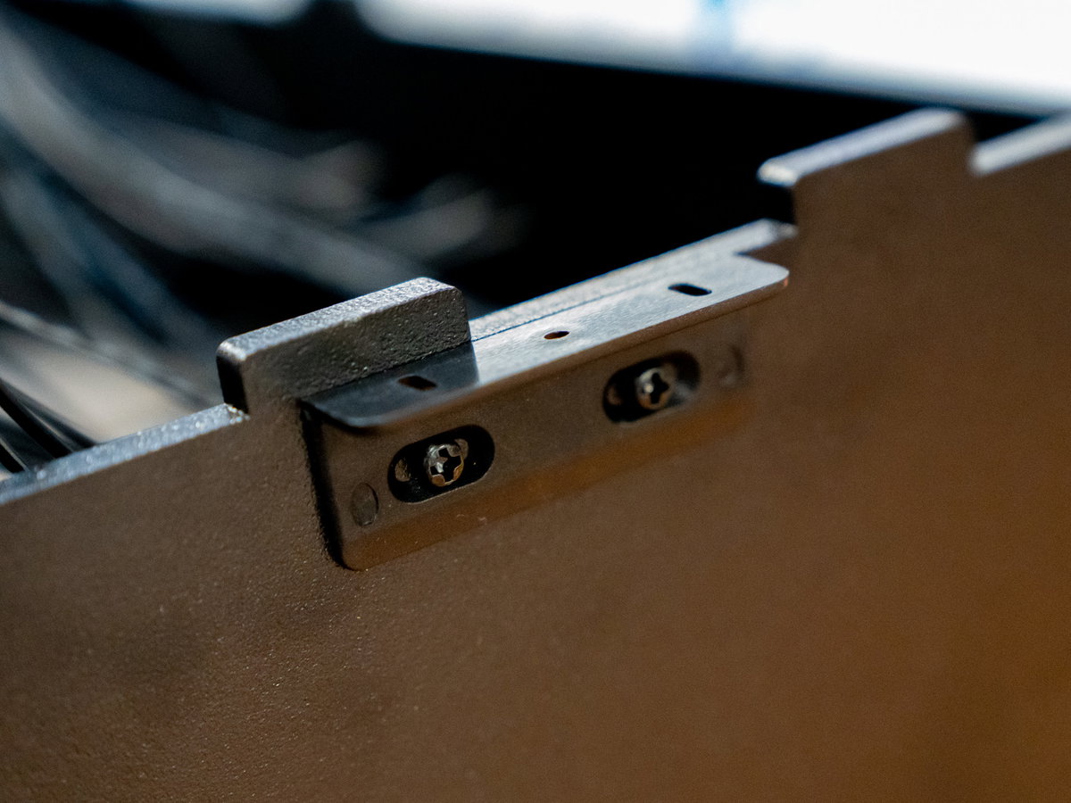
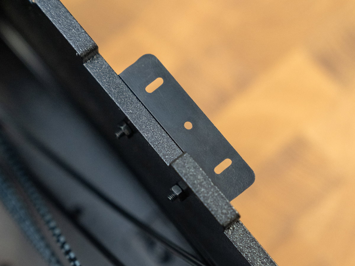
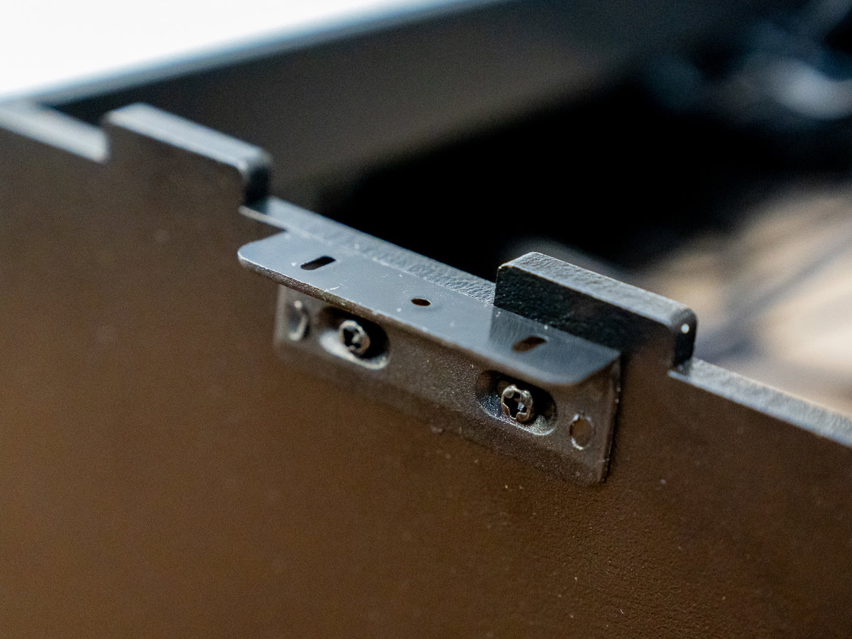
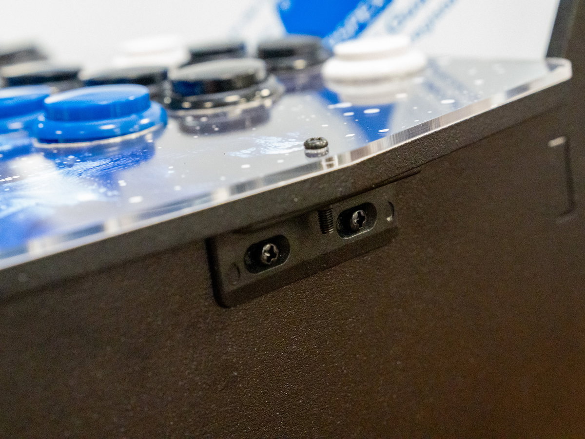
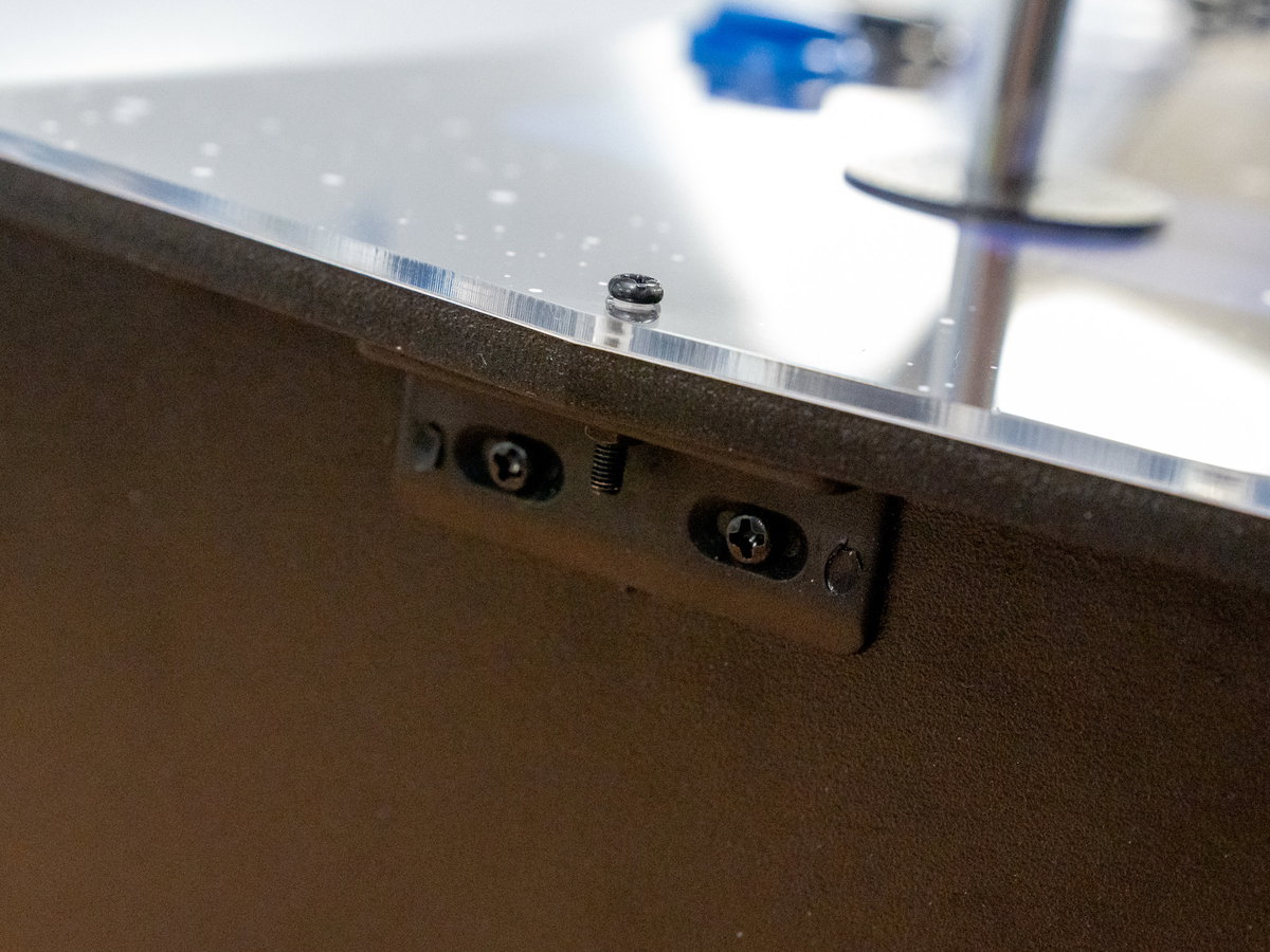
Fix the console assembly in place using the long M3 18mm screws and the side brackets.
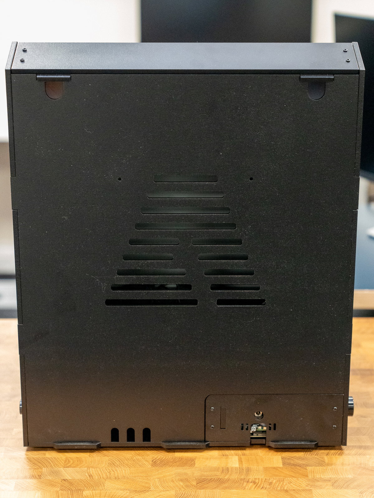
Slot the tabs in the back panel into the slots on the base and back. The wooden tabs at the top should hold it in place securely.
Time to unpeel any remaining protective coating from the acrylic screen and marquee pieces (savour this moment!)
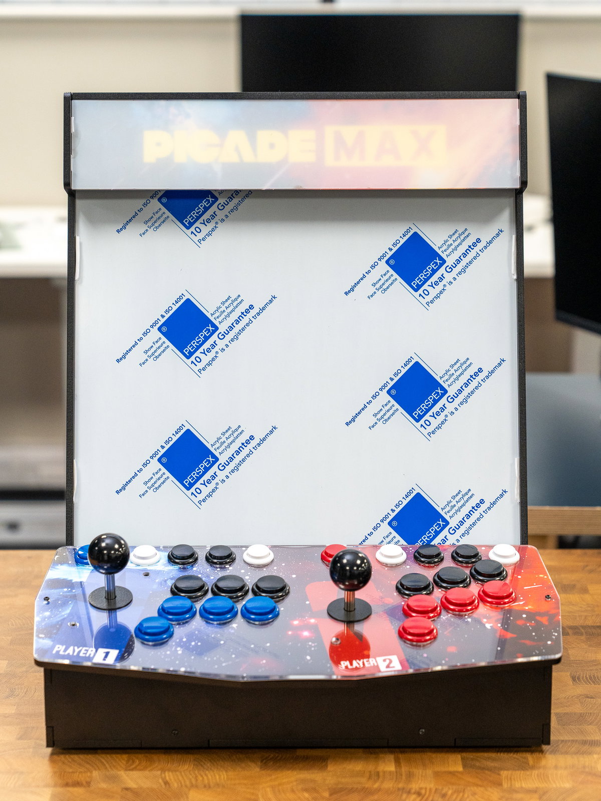
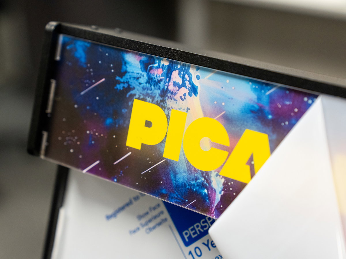
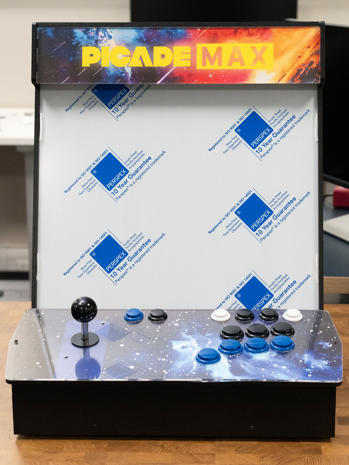
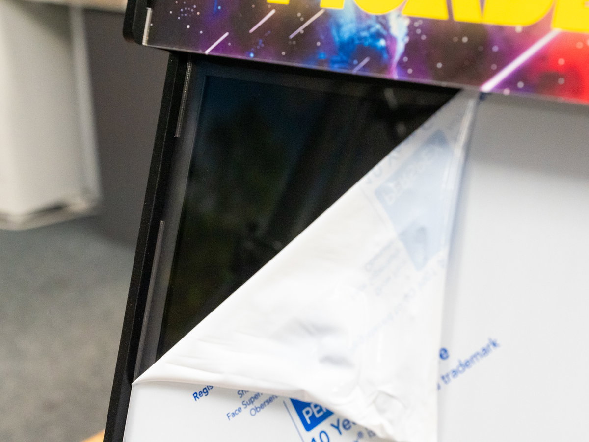
We are done with the assembly! Take a moment to step back and admire your work. Then connect the PSU to the cabinet and see if it works!
Software Guide
You can find our guide showing you how to set up the software side of Picade Max below:
Feedback
We hope you enjoyed building your Picade! We'd love to know if you encountered any issues during the build and if you have any suggestions for how we can improve the kit and this guide - you can drop us an email at picademaxbeta@pimoroni.com. We'd also really like to hear about it if you make any cool modifications to your Picade Max. You can discuss all things Picade Max on our forums or our Discord!